


HYDRAULIC STEERING GEAR.
Page 30
If you've noticed an error in this article please click here to report it so we can fix it.
A Resume of Recently Published Patents.
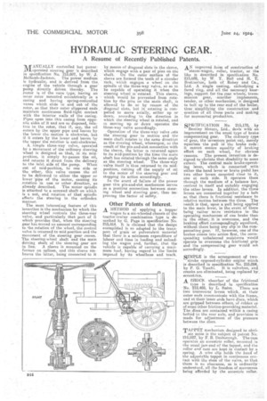
WNUALLY controlled but poweroperated steering gear 's described in specification No. 215,607, by W. J. MeIlersh-Jackson. The power medium is hydraulic, and is _derived from the -engine of the vehicle through a gear pump directly driven thereby. The motor is of the vane type, having an inner rotor mounted eccentrically in a casing and having spring-controlled vanes which slide in and out of the rotor, so that their outer slippered ends maintain continaous fluid-tight contact with the interior walls of the casing. Pipes open into this casing from opposite sides of it and are so disposed, relative to the rotor, that if, say, the oil enters by the upper pipe and leaves by the lower the motion is clockwise, but if it enters by the lower and leaves by the upper the rotation is anti-clockwise.
• A. simple three-way valve, operated by a movement of the ordinary steering Wheel is designed so that, in its mid. position, it simply by-passes the oil, and returns it direct from the delivery to the inlet, side of the pump. When out of raid-position, to one side or the other, this valve 'causes the oil to be delivered to either the upper or lower 'pipe of the motor, causing its rotation in one: or other direction, as already described. The motor spindle is attached to a screwed shaft on which is a nut, and rotation of that spindle effect-s the steering in the orthodox manlier.
The most interesting feature of this invention is the mechanism by which the steering wheel controls the three-way valve, and particularly that part of it which provides that, when the steering gear has moved an amount corresponding to the rotation of the wheel, the control valve is returned to mid-position and the movement of the steering gear ceases. The steering-wheel shaft and the main driving shaft of the steering gear are
in line. A sleeve is mounted on the former on splines' and this sleeve embraces the latter, being connected to it
by means of diagonal slots in the sleeve, which engage with a pair of pins on the shaft. fill n the outer surface of the sleeve are formed the teeth of a circular rack, which engages a wheel on the spindle of the three-way valve, so as to be capable of operating it when the steering wheel is rotated. This sleeve, which would be prevented from rotation by the pins on the main shaft, is allowed to do se by reason of the diagonal slots, but in rotating is compelled to move axially, either up or down, according to the direction in which the steering wheel is rotated, and in moving up or down operates the three-way valve accordingly. Operation of the three-way valve eets the steering gear in motion and the main shaft rotates in the same direction as the steering wheel, whereupon, as the result of the pin-and-slot connection with the sleeve, the latter is returned again to its mid-position by the time the main shaft has rotated through the same angle as the steering wheel. The three-way . valve itself is thus returned to its mictposition, cutting off the supply of oil to the motor of the steering gear and stopping its action accordingly.
In the event of failure of the newer gear this pin-and-slot mechanism serves as a positive connection between steering wheel and steering gear, thus improving the factor of safety.
Other Patents of Interest.
A METHOD of applying a hopper wagon to a six-wheeled chassis of the tractor-tralier combination type is described by G. Page in specification No. 215,414. It is claimed that the design exemplified is so adapted to the transport of grain or pulverulent material that there is a minimum expenditure of labour and time in loading and unloading the wagon and, further, that the vehicle is capable of carrying a mar'mum load, having regard te the limits imposed by its wheelbase and track
AN improved form of construction of
steam-wagon, roller, tractor, or the like is described in specification No. 215,689, by W T. Bell and H. T. Bretlierton, both cf Robey and Co., Ltd. A single casting, embodying a faced ring, and all the necessary bearings,. support for the rear wheels, trans: mission gear, scantier implements, tender, or other mechanism, is designed to bolt up to the rear end of the boiler, thus simplifying the construction and erection of all those parts and making for economical production.
SPECIFICATION No. 215,178, by
Bentley Motors, Ltd., deals with an improvement on the usual type of brake compensating gear. The ordinary type of gear, the inventors point out, merely equalizes the pull in the brake rods: it cannot ensure equality of braking effort on each wheel? for obvious reasons. The present invention is designed to obviate that disability to some extent.. The central main brarce-operating lever, which is connected with either the hand lever or brake pedal has two other levers mounted close to it, one at each side. It operates them through the medium of a balance bar, centred in itself and suitably engaging the other levers. In addition, the three levers are connected together by a bolt so that there is frictional resistance to relative motion between the three. The result is that, upon a pull being appliedto the main lever, in the event of there being rather mere resistance in tho operating mechanism of one brake than in the other, it is overcome, and the braking effort corresponelingly equalized, without there being any slip in the compensating gear. if, however, one of the brakes comes into action first, the corresponding unbalanced resistance would operate to overcome the frictional grip and the compensating gear would act accordingly.
SIMPLE is the arrangement olf two stroke opposed-cylinder engine which is described in specification No. 215,004, by P. G. Tacelii.11is valveless, and cranks are eliminated, being replaced by, eccentrics, A SHOCK absorber of the frictional type is described in specification No. 212,489, by L. Suere. There are two transverse levers which, at their outer ends communicate with the frame, and at their inner ends have discs, which are gripped between others, of rubber or of some other friction-provoking material. Tne..dises are contained within a casing bolted to the rear axle, and provision is made for adjustment of the pressure between the discs.
TAPPET mechanism designed to obvi ate noise is the subject of patent No. 235,037, by F. R. Desborough. The Cain operates an eccentric roller, meunted in the usual jaw-end of the tappet, and the roller and cam are kept in contact by a spring. A wire clip holds the head el: the adjustable tappet in continuous contact with the stem of the valve, so that there is no clearance, as is ordinarily understood, all the freedom of movement being afforded by the eccentric roller.