


BODY ROLL ONE OF THE P. V. DESIGNERS' BIG WORRIES
Page 26
Page 27
Page 28
If you've noticed an error in this article please click here to report it so we can fix it.
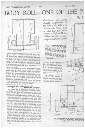
Centrifugal Force .Causes Angular Displacement of the Bulk of the Vehicle in Relation to its Axles. This is Called Body .Roll, and it Presents a Difficult Design Problem Specially' in Connection with Dduble Deckers :Three Different Systems of Suspension Are Considered, and Their Respective Features, in so far as they Affect Roll, are Compared. The Author also Expresses His Views on Stabilizing Devices and Their Effect THE ever-improving performance of modern passenger vehicles accentuates difficulties 'which have hitherto been regarded as of no great importance. The spring pwblems of a vehicle travelling at high speed are diverse, and often -at variance one with another, leading to the usual compromise most marked in the orthodox, and few designers have had either the courage or the opportunity to embody in commercial chassis the more advanced designs now being' introduced tothe
piivate car world. .
One of the most serious factors, particularly in doubledecked buses, is wliat is known as roll, or the angular displacement of the bulk of the vehicle, in relation to its axles, due to centrifugal force. Expressed maiMematically, body roll, for any given speed and turning circle, depends directly on the height of the centre of gravity above the roll centre, and the spring rate, and varies inversely as the spring-base width.
For pr.tctically all suspensions, except the parallel action independent type (Fig. 1), the roll centre lies midway between the axle spring anchorages, Definition of Terms Needed to • Study the Problem Roll centre may be defined as the point which is not subject to lateral displacement, but only rotation, whilst roll axis is the line connecting the roll centres of both axles. This is a feature which must be takeit into account when considering the vehicle as a whole.
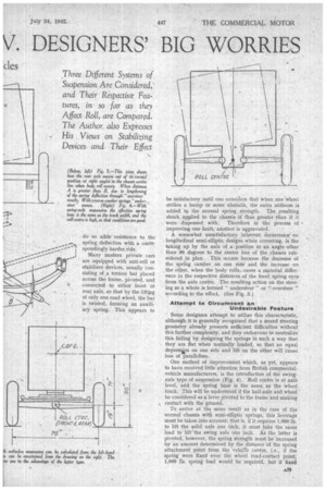
On examination of a bus chassis, it will be noticed that the rear springs are spread'wide apart, but in order to reduce the frame height, they are underslung, thus lowering the roll centre and increasing the roll moment (Fig. 2). The front springs are arranged with a comparatively narrow base, which is determined by the need for clearance of the wheels when on full lock. Although this unsatisfactory condition is, to some extent, mitigated by the springs being placed aboVe the axle bed, the necessity of a dropped axle to clear the sump still brings the roll centre well below the wheel centres.
There appears to be little that .can be done with an orthodox suspension without interfering with loading height, spring travel, engine-sump clearance, etc., for, if the springs are designed to give good riding conditions (that is, ideal suspension characteristics when a vehicle is travelling straight ahead), they will most probably be too flexible to react favourably when subjected to roll moment forces. It is, therefore, necessary to compromise, using springs that are too hard in respect' of ride and too .soft with regard to roll.
The addition of shoc k absorbers or the stiffening of existing ones does not reduce roll, but merely slows down the displacement; moreover, to
do so addsresistance to the spring deflection with a correspondingly harder ride.
Many modern private cars are equipped with anti-roll or stabilizer devices, usually consisting of .a torsion bar placed across the frame, pivoted, and connected to either front ot rear axle, so that by the lifting of only one road wheel, the bar is twisted, forming an auxiliary sprirtg. This appears to be satisfactory until one considers that when one wheel strikes a bump or some obstacle, the extra stiffness is added tc, the normal spring strength. The resulting shock applied to the chassis is' thus greater than if it were dispensed with. Therei ore in the process of improving one fault, -another is aggravated.
A somewhat unsatisfactory inherent dccurrence on longitudinal semi-elliptic .designs when cornering, is the taking up by the axle of a position at an angle other than 90 degrees to the centre line of the chassis considered in plan. This occurs because the decrease of the spring camber on one side and the increase on the other, when the body rolls, cause a material difference in the respective distances of the fixed spring eyes from the axle centre. The resulting action on the steering as a whole is termed " understeer " or `: oversteer " according to the effect. (See Fig. 3.)
Attempt to Circumvent an Undesirable Feature
Some designers attempt to utilize this characteristic, although it is generally recognized that a sound steering geometry already presents sufficient difficulties without this further complexity, and they endeavour to neutralize this failing by designing the springs in such a way that they are fiat when normally loaded, so that an equal depressip on one side and lift on the other will .cause loss of parallelism.
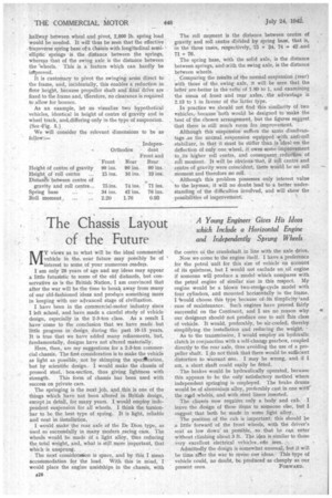
One method of improvement which, as yet, appears to have received little attention from British commercialvehicle manufacturers, is the introduction of the swingaxle type of suspension (Fig. 4). Roll centre is at axle level, and the spring base is the same as the wheel track. This will be understood if the half-axle and wheel be considered as a lever pivoted to the frame and making contact with the ground.
To arrive at the same result as in the case of the normal chassis with semi-elliptic springs, this leverage must be taken into account; that is, if it requires 1,000 lb. to lift the solid axle one inch, it must take the same load to lift' the swing axle one inch. As the latter is pivoted, however, the spring strength must be increased by an amount determined by the distance of the spring attachment point from the vehicle .centre, i.e., if the spring were fixed over the wheel road-contact point, 1,000 lb. spring Toad would be required, but if fixed halfway between wheel and pivot, 2,000 lb. spring load would be needed. It will thus be seen that the effective -transverse spring base ota chassis with longitudinal semielliptic springs is the distance between the springs, whereas that of the swing axle is the distance between the -Wheels. This is a feature which can hardly be irflproved.
It is customary to pivot the swinging arms direct to the frame, and, incidentally, this enables a reduction in flcror height, because propeller shaft and final drive are fixed to the frame and, therefore, no clearance is required to allow for bounce.
As an example, let us visualize two hypothetical vehicles, identical in height of centre of gravity and in wheel track, areldiffering only in the type of suspension. (See .Fig. 5.)
We will consider the relevant dimensions to be as follow:—
The roll moment is the distance between centre of gravity and roll centre divided by spring base, that is, in the three cases, respectively, 75 434, 74 4. 42 -and 71 76.
The spring base, with the solid axle, is the distance between springs, and with the swing axle, is the distance between wheels.
Comparing the results of the normal suspension (rear) with those of the. swing axle, it will be seen that the latter are better in the ratio of 1.89 to 1, and examining the mean of front and rear axles, the advantage is 2,13 to 1 in favour of the latter type.
In practice we should not find this similarity of two vehicles, because 'both would be designed to make the . best of the chosen arrangement, but the figures suggest that there' is still much room for. improvement.
Although this suspension suffers the same disadvantage as the normal suspension equipped with anti-roll stabilizer, in that it must be stiffer than isldeal on the deflection of only one wheel, it owes some improvement to its higher roll centre, and consequent reduction of roll monient It will be obvious that, if roll centre and centre of gravity were coincident, there would be no roll moment and therefore no roll.
Although this problem possesses only interest value to the layman, it will no doubt lead to a better understanding of the difficulties involved, and will show the :possibilities of improvement