


Saurer Oil-engine Developments
Page 58
If you've noticed an error in this article please click here to report it so we can fix it.
TwOpatents are disclosed, this week, by S. A. Adolphe Saurer, of Arbon, Switzerland, each describing improvements. in the design of oil engines for vehicles.
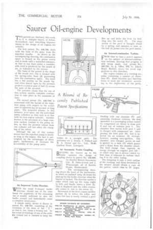
The first patent, No. 448,758, deals with the form of the spray from the
injection nozzles. As shown in the accompanying drawing, the combustion space is formed in the piston crown and is made with a restricted entrance, so that at top dead centre a Considerable :swirl is produced by the inrush of
air, as indicated by the arrows. •
The basis' of the patent is the shape of the nozzle end; this is formed with the spring-valve head (2) protruding into the combustion space. The head. has a flat seating on the nozzle tip, and when forced open by the pressure projects a conical mist of fuel (I) across the, path of the air-swirl.
The patentee claims that the use of this system enables complete combustion to take place in the minimum of time.
The second patent (No. 448,759) is concerned with the layout of the injection pump with respect to the avoidance of injection lag on account of long pipes. The proposed scheme, in this instance, is to space out the individual pump cylinders so that each is in line with, its own engine cylinder. Another feature is the provision of a large common suction conduit to the pump inlets, so that the pressure release from one cylinder will not affect the charging of the others.
Although the use of this system means that the injection pump is nearly as long as the engine, this fact is outweighed by the advantages of short pipes; furthermore, it increases the accessibility of the pump units.
An Improved Trailer Drawbar.
WITH the usual Y-shaped trailer drawbar, should one of the arms break the angularity of the remaining one is usually sufficient to slew the trailer around and immediately cause a complete break-away.
A simple safety device is shown in , patent No. 448,724, consisting of the extension of the stem of the " Y " so that it, too, forms a tension rod. In the event of breakage of one of the arms the central rod is claimed to keep the B44 trailer to a straight path. The patentees are J. Dyson, T. Pollard and R. A. Dyson and Co., Ltd., 76-80, Grafton Street, Liverpool.
An Automatic Trailer Coupling.
D ACE ENG the tractor up to the ',trailer operates the design of coupling shown in patent No. 448,866, by Karrier Motors Successors, I Ltd., R. Dean-Averns and J. Whattnough, all of Karrier Works, Huddersfield.
The accompanying drawing shows the heart of the mechanism, in which an inclined ramp (5) forms the pick-up for the trailer drawbar when the tractor is backed. The drawbar carries a roller which runs up the ramp (right to left) and finally meets a lever (2). This is displaced and the roller eventually comes to rest in the recess (I).
Movement of the lever causes another portion (3) to follow the roller, and when this face is nearly vertical a pawl flies up and locks the lever by bed.
ding into the notch (7). The snap action of the pawl is brought about. by a spring, and operates so soon as the link (4) passes over the pawl centre.
An Internal-combustion Turbine.
FROM time to time a patent appears. on the subject of internal-combustion turbines, showing that progress is still being made, and patent No... 445,550, by A. Offen, 102, St, John's. Road, Redhill, shows the latest suggestions in this direction.
The engine consists of a rotating annulus containing a number pf chambers (7). Each chamber may function twice or more per revolution, according to the duplication of the parts.
Dealing with one chamber (7) and assuming clockwise rotation, the first.' operation is a scavenging action caused by compressed air blown in from port 6 and out of exterior, port 1. Thefl chamber then moves from port 1 and is charged with compressed air. After passing the inlet port (6), fuel is injected via an atomizer (5) without, however, causing auto-ignition. The chamber, now charged, passes on and . is ignited by a tube (3) which passes over a flame from the chamber ahead. The fired charge then expends its energy through an angular port (2)— of which only one is shown—which by that time is adjacent to turbine blading 4 in the outer casing.
The foregoing is only a brief outline of the working, and those interested in the subject should obtain a copy of the patent, which ruins to 15 pages.