


FOUR-WHEEL STEERING OF A TRACTOR LORRY.
Page 12
Page 13
If you've noticed an error in this article please click here to report it so we can fix it.
Improving the Manoeuvrability of the Six-wheel Tractor Lorry by Making the Rearmost Wheels, as well as the Foremost Steer.
ADEVICE has recently been patented and perfected by Carrosserie Latymer, Ltd., whereby the rearrnoet wheels of a tractor lorry are oaus4d to track with the other wheels when a corner is negotiated. It is well known that, in the ordinary way, the rear wheels of a lorry cut across the track of the front wheels and in the tractorlorry, the rearmost wheels cut across still farther; this is a distinct disadvantage andinvolves swinging out on corners to avoid bringing the wheels across the kerb.
• Many attempts have been made to -overcome this difficulty, in most of which the rearmost wheels., were coupled up with the front steering wheels. This plan has seVeral inherent disadvantages. To.,begin with, it increases the labour involved in steering the vehicle and the . complexity of the inechan'sin. Further, if the-vehicle is drawn up beside a kerb, so soon as the driver turns the front . wheels in order to move away from the kerb the rearmostwheels turning in vie opposite direction, tend wheels, run towards
it. ' • .
These difficulties have been successfully overcome in the system under review, which is automatic in action and is controlled by the relative angularity of the tractor and trailer portions of the vehicle. We -understand that the device is primarily intended for the chassi,s of a six-wheeled, bus, but is, of course, .applicable to any form of tractor-lorry where mancenvrability is of prime im
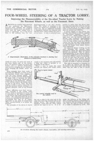
portance. • The principle of the device is shown
diagrammatically in the first illustration.The trailer is attached to the 'tractor by means of a turntable in the usual way, but an additional turntable is interposed between the rearmost axle and the frame, which enables this axle to swivel freely. A tube is attached trans
versely to the rearmost axle end contains a long rod, which is pivoted to an extension of the taacter.
When a turn is made, the angle between the tractor and trailer causes the rod to slide in the tube and at, the same time turns the rearmost axle in the manner shown. The rearmost wheels, therefore, track with the other wheels and de not tend to cut in. It is iirt portent to notice that this device does not come into operation until the tractor and trailer are set at an angle to each other, so that starting away from a, kerb does not present any difficulty. • . • A device similar to that shown has actually been fitted to vehicles supplied by Carresserie Latymer, Ltd., for Colonial work. These vehieles were of a light type, and for heavier loads and British road conditions improvements Were obviously desirable. For example, with the long trailers used on a 12-ten vehicle the rod and tube would become of unmanageable Size and would project outside the frame when ,sharp corners were negotiated.
An improved design working on the Same principle has recently been patented in which the above-mentioned defects are obviated, This is shown diagrammatically in the second illustration, and its application to the Carrimore tractor-bus chassis. is given in elevation. It will be seen that the pivot on the tractoris only a short distance behind the axle and that the tube in which the pivoted rod slides is likewise shortened.
This tube is mounted on trunnions so as to allow for relative up and down movement of the three axles, and at the same time the tube is free to swivel
under the influence of the sliding rod. This swivelling motion is transmitted to the rearmost axle by means of a pair of rods, after the style in which the tiller of a rudder is operated by cords. The principle is, therefore, exactly the same as that shown in the first diagrammatic illustration;' hut, owing to the position and shortness of the sliding rod and tube, there is no tendency for these parts to project beyond the chassis, no matter what the relative, positions of the tractor and trailer may be This device should greatly improve the 'ease with which abrupt corners can be negotiated on this type of vishiclk and Garrosserie Latymer, Ltd., hope that it will assist them in their endeavour to get legal sanction for the running of " tractor-buses." The greatest angularity of the rearmost
swivelling axle is reached when the tractor and trailer are at right angles, 'and it is interesting to notice .that, if further movement were possible between the two parts of the vehicle, this wonld tend to deqease the angularity of the axle instead of increasing it,
The elevation shows that the rearmost axle and its half-elliptic springs form a unit which is mounted on a large turntable. In order to avoid the complexity which would be inevitabie if mechanically controlled brakes were used, the vehicle is equipped with the Westinghouse air-brake system, and this, of course, carries with it the additional advantage that practically no exertion is entailed in applying the brakes.
If the running of six-wheel or traderbuses becomes legalized, the firm has an excellent design of body ready for this chassis which will provide seating accommodation. for 50 people and will be capable of carrying ten "straphangers " in addition. The capacity will, therefore, he equal to the latest type of large double-deck buses, with, of course, a much less -height. ThiS should appeal to concerns running .uses in districts where low bridges ex'.st. The body was illustrated in T orianttrcial Motor a short time ago.