


The New Pagefield Subvention Model.
Page 62
Page 63
Page 64
If you've noticed an error in this article please click here to report it so we can fix it.
A Very Interesting Chassis Which Bears Evidence a Original and Practical Design to an Unusual Extent.
Tin a leading article, in our issue of the 26th ult., we mentioned that, among the candidates for the subventiol certificate at the next War Department trials is Walker Bros., Ltd., of the Pagefield Iron Works, Wigan, which company has designed and built a vehicle to comply with the War Department's specification for chassis capable of carrying a gross load of 41 tons, and the first of the new type will be found to be the principal exhibit of its maker at the present Show at Olympia.
A Down-swept Frame.
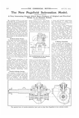
The high bonnet and radiator demanded by the War Department does not look so extraordinarily high on this new model of Walkers, as they have resorted to the use of a special pressed-steel frame, down-swept at the forward end, so as to drop the bonnet and radiator and reduce their apparent height. Notwithstanding the sweep in the frame, the side members are remarkably strong, and the whole frame is so well stayed and braced as to remove any anxiety whatever on the score of its whipping or distorting.
The separate mounting of the complete units and their interconnection, by means of universallyjointed shafts, is a most commendable feature on this chassis. There has been no crowding together of parts, the result being that it is perfectly easy to dismantle any one unit without disturbing other parts.
Careful Cylinder Design.
The engine, it will be noted, is one of the four-cylinder type, with cylinders cast in pairs, and all the valves arranged to be actuated from one camshaft. The cylinders are 41 ins, in diameter, and the
piston stroke is 51 ins. The design of the cylinders has evidently been carefully considered, with a view to the elimination of fiat horizontal surfaces on which steam or air bubbles may collect and give rise to local overheating, and the crosspassage for the induction gases has been made of elliptic cross section, whilst, in longitudinal section, it is much deeper in the middle than at the two ends, so that its under-surface is sloped upwards from both sides and from the middle, and there is, therefore, no opportunity for air-lock at this point, a trouble which we have experienced with a number of engines of the type in which all the valves are arranged on one side. Each valve pocket is completely water-jacketed. with a view to the prevention of distortion of the valves or their seats. The valve stems and springs, it will be noted, are enclosed by means of aluminium covers, thus presenting a clean and finished appearance, and eliminating, or, rather, muffling, any noise that may arise from the action of the tappets.
The baseplate of the engine is a massive casting, amply webbed and stayed, and is arranged to carry the crankshaft bearings, as well as the camshaft bearings. The continuous side webs of the baseplate are extended, and form bearers for the engine, which is carried from a substantial subframe. Very large inspection doors are provided, and each pair of doors may easily and quickly be removed.
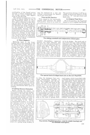
A Sliding Camshaft.
The camshaft and bearings, of which we reproduce a longitudinal sectional drawing, is arranged for sliding in an endwise direction, so as to bring compression-release cams into operation to facilitate
s. Tt will be noted that the drive is .0...emitted to the camshe irom one of the two geese ',eels shown, through a sleeve, which is journaled in a substantial fixed bearing; this sleeve is provided with two single ball-thrust bearings to take up the endpressure when the shaft is being moved, in either one direction or the other. The trip lever, for controlling the compression release, is carried out to the front of the frame, in a convenient position for starting. The back end of the camshaft, as will be seen, like the forward end, is fluted, and passes through the hub of a bevel pinion which meshes with another bevel pinion on a short vertical shaft ; on the top end of this latter shaft the governor is mounted, whilst the lower end is connected to a gear type of lubricating-oil pump, the system of lubrication being a
combination of the forced system through a hollow crankshaft, and the trough system, with dippers fixed on the big-ends. The general arrangement of the engine is clearly shown in one of the illustrations which we reproduce, and a reference to that drawing will show that there is an alu minium apron, or tray, attached to the forward end of tle crankcase, for the purpose of carrying the starting-handle bearing and the compression-release lever, and to close in the space between the front transverse member of the frame and the main portion of the crankcase ; there is, thus, no need whatever for the fitting of a mudshield forward of the clutch.
A Tilted Magneto.
Referring back to the longitudinal view of the camshaft, it will he noted that two gearwheels are shown ; the larger of these two is a straight spur gear, which receives the drive from the crankshaft pinion, whilst the smaller of the two is a helical wheel, which meshes with a smaller helical wheel on a transverse shaft ; the transverse shaft is tilted at an angle of about 30 degrees, and the upper end is coupled to the magneto, whilst the lower end is coupled direct to the centrifugal water pump. The object of mounting this shaft diagonally has been to bring the magneto into a very accessible position ; it is not necessary to grovel on one's hands and knees, or to crouch down between the front win, in order to effect any adjustments or cleaning of the make-andbreak gear. Another advantage, arising from the diagonal mounting, is that the water passage from the pump to the cylinders is most direct, and sharp bends are completely eliminated, so that, in the event of the failure of the pump, the engine will continue to cool on the therme-syphon principle, without any detrimental effect upon its running.
A Lighting Dynamo Embodied.
Before leaving the engine, we would particularly call our readers' attention to the fact that the design includes, as part-and-parcel of one co-operative whole, a means of mounting and driving any type of electric-lighting dynamo which a user may desire to fit. This is a commendable feature, as so often the lighting system is considered by manufacturers as a mere adjunct to the chassis, and when a dynamo has to be fitted it is often More or less a " botched " job.
The well-tried lined cone type of clutch has been adopted, and there ik nothing remarkable about its construction, except that, instead of a single central helical spring, three separate helical springs are fitted ; these are arranged in such a way that, not only is adjustment a perfectly easy matter, but, in the event of a spring being broken, it
may he replaced by a new one without necessitating the disturbing of any other part.
Trays on the Gearbox.
With regard to the universallyjointed shaft between the clutch and gearbox, there is no need for detailed description ; approved practice has been followed., and the parts are well proportioned to sustain any load that may be imposed upon them. The same remark applies to the gearbox, which, it will be seen by reference to the drawings, is of very sound construction, with constant-mesh gears for all except the first speed and reverse, and, in order to avoid having long shafts, which are likely
to whip, the designers have provided intermediate bearings on both the mainshaft and the layshaft. The width and pitch of the gears are such as to remove any anxiety of users on the score of excessive wear. At each end of the gearbox, below the bearing .covers, trays are cast integral with the gearbox, so that, should a user prefer to run his machine without an undershield, any drip from the bearings would be caught in these trays or pockets, instead of dropping on the road or garage floor. The provision of trays, it will be recalled, is one of the features of the L.G.O.C. " B " type gee-, boxes and back axles.
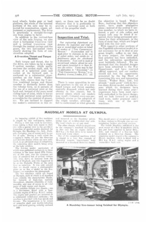
An Original Final Drive Aft of the gearbox, the Pagefield chassis is meet original and practi cal in its design. The back axle is one of the live type, with a doublereduction sear; the first is a substantial pair of bevels, and the final drive is from a differential countershaft through spur gears to the axle shafts. The whole of the imposed load on the chassis is carried by a solid forged axle, of the shape shown in the separate line drawing which we reproduce, and to the front of this axle is bolted a cast steel easing, which is provided with a suitable housing and bearings for the main-drive bevel pinion ; to the back of the axle is fixed an aluminium case, which carries bearings for the differential countershafts. The hearings for the inner ends of the differential shafts are mounted in housings that are spigotted into, and bolted to, the solid axle forging. A brief study of this construction will show that, although exceptionally strong, it is comparatively light in weight, and, without disturbing the cast-steel road. wheels, brake gear or load platform, the whole of the internal portions of the axle may be removed for examination, repair, adjustment or replacement. The drive is practically a straight-through one from engine to bevel.
In. /addition to the vertical-face view of the axle forging, we also show a horizontal transverse view and a vertical transverse view through the central casings and the gears, the two last-named views clearly showing the form of construction adopted.
A U-section Thrust and Torque Member.
Both torque and thrust, due to the drive, are taken up by a single U-section member, which partly encloses the eardan shaft, and, by means of a spherical joint and socket at its forward end, is anchored to a substantial crossmember on the frame. Walker Bros., Ltd., claims that the U-seetion combined torque and thrust member is distinctly better than the tubular form, as it permits of the use of a universal joint at the back end, instead of the more usual sliding type of joint, while it leaves this back universal joint perfectly accessible for the renewal of grease, etc. We are inclined to support the maker's contention in this re
spect, as there can be no doubt whatever that it is preferable to provide a universal joint at both ends of the preepeller shaft.
There is some opposition in certain quarters to the use of a combined torque and thrust member, centrally disposed, which not only obtains in this chassis, but in several others which our readers may recall ; Colonial users are particularly averse to the adoption of the single member, although we fail hi understand on what grounds the objection is based. Walker Bros., realizing that this objection exists, have made alternative plans ; instead of the central IT-section member, to which we have referred, a pair of side radius and torque rods may be fitted if requirsd, there being permanent provision for their attachment, in the form of stout lugs, which are forged solid with the rear axle.
With regard to other portions of the Pagefield subvention model,it is not necessary for us to deal at any great length ; suffice to say that, in every respect, the latest and best practice has been embodied, and the subvention specification most faithfully followed. We understand that the detailed designs have been submitted to the War Department, and have received official approval, and our readers should not lose the opportunity presented by the big Show of examining this new and interesting chassis. -Walker Bros., Ltd., has already "made good" with its twoton chain driven model, and the lessons which its designers have learned during their many yeari' experience have been most earifully embodied in the latest design, and we look forward to makin; road tests, under practical cond 1tions, with one of the new machines.