


Four Speeds Forward and Three Reverse ik ANY utility vehicles—dumpers,
Page 54
If you've noticed an error in this article please click here to report it so we can fix it.
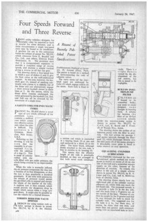
for Mexarnple—may he required to work in reverse for some distance, and in these circumstances a single low-speed ratio may be found to be insufficient. A gearbox for use in this connection forms the subject of patent No. 582,295, which emanates from E. Boydell and Co., Ltd., and others, Elsinore Road, Manchester, 16 The patentees state that it is comparatively expensive to provide a complete range of reverse speeds, and disclose a simple method giving a reverse to all but top gear.
The drawing shows a four-speed box in which a pair of sliders (1 and 2) give the four ratios in the well-understood manner. In this case, however, the layshaft gear (3), instead of meshing constantly with rinion 4. is slidably out of the latter and can alternatively engage a short reverse layshaft shown in chain lines at 5. By this means, whilst the direct drive remains unchanged, the ratios governed by the layshaft (1st, 2nd, and 3rd) can all be reversed by the movement of a single lever.
A SAFETY CORE FOR PNEUMATIC TYRES
PATENT No. 581,810 shows a novel type of tyre which, although of the pneumatic I y p e, contains a resilient core which comes into effective action only when the tube is deflated. The patentee is J. Urmston, Montclair, New Jersey, U.S.A.
Referring to the drawing, it will be seen that the assembly is of conventional f o r m, with the addition of a ring (I). This is made of cellular rubber with the cells filled with gas under pressure, the whole being covered by an impermeable skin.
When the tube is normally inflated, the air pressure compresses the ring into a fraction of its free dimensions, so that the tyre is then practically a standard pneumatic. If the tube were punctured, the release of pressure would permit the gas-filled cells to expand and occupy the whole of the interior of the tube. A cushion tyre is thus created, which would prevent the dangerous drop in height which occurs when a large tyre goes down. It might also be possible to run the vehicle for a limited distance.
TORSION RODS. FOR VALVE SPRINGS A DESIGN for using torsion rods a3 1-1. valve springs is shown in patent No. 581,714, by S. A. des Anciens
Etablissements Panhard et Levassor, 19, Avenue d'Ivry, Paris. The patent is based on a method of interconnecting the rods of adjacent valves.
The valve stems (of the overhead type) are embraced by forks (I) which engage collars on the stems. Each fork is fixed to
a torsion rod which is journalled in a bearing block (2) at one end and anchored in a block (3) at the other. The latter block, although firmly attached to the two rods, is free to revolve in its housing (4).
This means that the effective length of the rods is practically doubled, as they are arranged so that both never work simultane ously. There is a slight flexure caused by the displacement of the rod centres, but this is stated to be negligible.
BUILT-IN INJECTION-PUMP FILTER
CILTERS are
bound to be somewhat bulky, and seem to cause designers some thought in locating them. A scheme for housing the filter of an oil-fuel system actually inside the injection-pump casing is shown in patent No. 581,277, by C.A.V., Ltd., K. Brook and F. Evans, all of Warple Way, Acton. The drawing shows the outline of an injection pump with the filter in position. The fuel atrives via passage 1 and passes upwards through the filterpack (2), which discharges directly into the inlet ports (3) of the pump plungers. A detachable cover plate is fitted to make renewal an easy operation.
EQUALIZING CYLINDER LUBRICATION
YLINDERS lubricated by the con ••ventiorial splash method are rather prone to receive an excess of oil on one side of the wall and a somewhat meagre -supply on the other, because of the direction of rotation. To remedy this defect is the aim of a simple scheme shown in patent No. 581,315, by R. A. Lister and Co., Ltd., and A. Mellerup, both of Dursley, Glos.
The drawing shows clearly how the right-hand side of the cylinder receives adequate oil, whilst little can reach the left-hand side. The proposed remedy is to provide a hole (1) in the dry side, and this leads from a V-groove cut on the outside of the liner. Thrown oil can then be caught by the V-groove and find its way through the hole to reach the cylinder wall. The suggested size for
the hole is in., but there may, of course, be more than one hole, and more than one groove each communicating with an associated hole or holes.