


VEHICLE SUSPENSION ,TEMS OF THE FUTURE.
Page 50
Page 51
Page 52
Page 53
Page 54
If you've noticed an error in this article please click here to report it so we can fix it.
Developments in Springing are Continual the Present Time. The Pros and Cons o king Place, but Never More Rapidly than at bus New Systems are Discussed at Length.
JN recent issues of The Commercial Motor the allimportant problem of spring suspension has been treated fairly comprehensively, in non-technical language. It has been shown how comfort is really the governing factor in correct suspension, and how difficult it is to estimate a degree of maximum "rate of change of acceleration" which will prove to be satisfactory for all the thousands of passengers that an ordinary public coach will have to carry during its useful life. Further, the merits of various types of spring have been discussed at length, likewise the question of damping and the methods of obtaining a graduated system. It is now proposed to deal with what the future holds in store. Will the six-wheeler become an all-pervading influence, and how can existing Systems be improved, so that less damage is done to the roads, whilst at the same time providing additional comfort for the passengers?
The New Problem of Suspension.
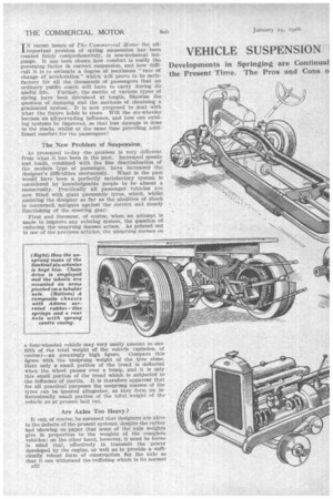
As presented to-day the problem is very different from what it has been in the past. Increased speeds and loads, combined with the fine discrimination of the modern type of passenger, have increased the designer's difficulties enormously. What in the past would have been a perfectly satisfactory system fs considered by knowledgeable people to be almost a monstrosity. Practically all passenger vehicles are now fitted with giant pneumatic tyres, which, whilst assisting the designer so far as the abolition of shock is concerned, mitigate against the correct and steady functioning of the steering gear.
First and foremost, of course, when an attempt is made to improve any existing system, the question of reducing the unsprung masses arises. As pointed out in one of the previous articles, the unsprung masses on a four-wheeled vehicle may very easily amount to onefifth of the total weight of the vehicle (unladen, of course)—an amazingly high figure. Compare this figure with the unsprung weight of the tyre alone. Here only a small portion of the tread is deflected when the wheel passes over a bump, and it is only this small portion of the tread which is subjected to the influence of inertia. It is therefore apparent that for all practical purposes the unsprung masses of the tyres can be ignored altogether, as they form an infinitesimally small portion of the total weight of the vehicle as at present laid out.
Are Axles Too Heavy ?
It can, of course, be assumed that designers are alive to the defects of the present systems, despite the rather bad 'showing on paper that some of the axle weights give in proportion to the weights of the complete vehicles; on the other hard, however, it must be borne in mind that, effectively to transmit the power developed by the engine, as well as to provide a sufficiently robust form of construction tor the axle so that it can withstand the buffeting which is its normal B32 lot when in use on the average road, the axle must be sturdy, and consequently of substantial dimensions,. which, of course, results in weightiness. .
A further use of aluminium alloy may be made for the easing, differential housing, etc., but this him of construction does not seem to be favoured, due to the fact that the section of the case has to he so thick, in
order to provide the requisite strength, that it appears-to be hardly worth while, the extra bulk mitigating against such items as ground clearance and the clearance between the top of the axle and the floor of the body. It seems, then, that an entirely different form of construction is required in order to make any material alteration in the ratio of " sprung " to " unsprung " weight.
At first sight chain drive seems to be the obvious solution, as the differential can be mounted in the chassis frame, with the driving shaf is protruding outwards to the chain sprockets. It is then a simple matter to arrange for the spring centres to be approximately in line with the centre line of the driving sprockets, so that the are described by the axle is approximately the same as the theoretical arc demanded by the chain in order to maintain it at a uniform tension.
In certain types of lorry this is commo.0 practice, whilst on one particular steam wagon a clever adaptation has been made of the principle to apply it to a four-wheeled bogie. We refer, of course, to the Sentinel D.0.6 chassis, in which a large-diameter tubular axle is mounted in the centre of semi-elliptic springs, arms extending fore and aft of this axle on each side containing the spindles for the wheels. Chain drive is employed from the engine to the forward wheels of Ole bogie, with additional chains to the rearmost wheels. In this way the wheels on each side of the axle can move independently, to compensate for the irregularity of the road surface, yet the total unsprung weight is small when compared with the total weight of the vehicle. It is not intended, however, to deal fully with the ultra-heavy vehicle.
Independent Wheel Springing for Passenger Vehicles.
Let us turn to a consideration of the medium and large-size passenger chassis. In the first place chain drive can be discounted altogether, as there are but few important examples of this type of final drive extant to-day. It has already been shown that with the normal type of shaft drive it is difficult to effect any material saving in weight, so that it is obvious that some other system must be evolved.
It is clear, then, that some form of independent springing must be introduced where the differential and final-reductien gearing will be sprung masses, whereas the wheels, and possibly a portion of the springs, will
be unsprung masses. The attainment of this ideal is not so simple as it might appear on the surface, for both driving and braking torques. have to be ta-ken care of, whilst side thrust is a difficulty which must be dealt with. Already there are one or two examples of independently sprung wheels, on both commercial and private-car chassis, but each appears to be different from the others, which seems to indicate that 'finality is still a long way off.
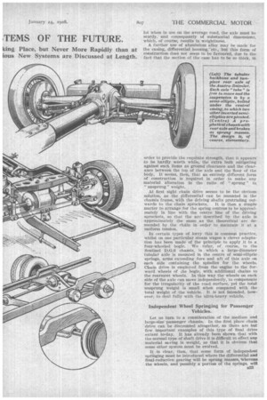
'Perhaps the simplest system of all, and one which, on paper at least, looks as though it would prove effective, is the Cottin et Desgouttes type of individual wheel suspension. This system calls for a centrally slung differential box, which, of course, is mounted actually on the chassis, with the axle shafts protruding outwards and connecting with the wheel hubs by unitersal joints. Quite rightly, the brake drums have been included in the differential-box unit, thereby cutting out more weight from the unsprung part of the assembly. Now, the wheel hubs are held in position by four springs, which might be termed double-acting cantilevers. They are grouped in a _box-like formation, with the front ends attached to extensions of the hub casing, the whole of this portion of the assembly being neatly tucked away within the dish of the wheels themselves. It will be seen, then, that the box-like formation of the springs provides quite a satisfactory method of transmitting the driving torque and absorbing the braking torque, despite the fact that leaf springs generally are not very strong when subjected to torsional loads.
The saving in unsprung -weight in a system such as that already outlined is enormous, for, apart from the wheel hubs, the wheels and tyres themselves, a small proportion of the axle shafts and a small proportion of the springs, all the rest is carried on the frame.
Perhaps the most outstanding example of independent wheel suspension is the system used at the rear of the Austro-Daimler tubular chassis, which was shown at the-Olympia Motor Show of last October. It is not suggested here that the tubular system of chassis construction employed in the Austro-Daimler chassis is suitable for large commercial vehicles, but the method of wheel suspension is ingenious and very interesting.
Bal A c tuall y three semi-elliptic springs are used as a means for suspension, the wheels being mounted on pivoted arms, which carry the wheels, with universally jointed axle Shafts located below the arms. Both the driving and braking torque reactions are taken through the arms and their bearings, the axis for which, of course, \ lies longitudinally along the centre of the chassis.
Another system that has been used on a small pleasure-car:. chassis for some time is the patented ,Steyr system, in which the differential and its casing are carried on a dished pressing attached to the rear end of the frame: Universally jointed axle shafts provide the drive to the wheels, the latter being located by strong radius rods the forward ends of which are mounted on a tube running across the chassis. In this system an inverted Semi• elliptic spring, which is virtually a double cantilever, is attached to the axle casing, the extremities of the spring being carried in pivoted shackles to permit the necessary transverse movement of the spring when it flexes. Again, whilst this system undoubtedly fulfils its purpose of reducing considerably the unsprung weight, it is doubtful whether arms or radius rods, as they might be termed, could be made sufficiently strong, yet light, reasonably to do the work imposed by a big commercial vehicle when filly laden. On the .other hand, a development might easily be made whereby the Coffin et Desgouttes and Steyr systems could be combined if it were found that the transverse springs of the former system were not strong enough to withstand braking and driving. torques.
Broadly speaking, then, the difficulty of reducing unsprung weight by mechanical means resolves itself into providing vertical elasticity and lateral rigidity, combined with adequate torsional strength to take the loads imposed by driving and braking. Are there no means by which the same result might be achieved but by using either pneumatic • or hydraulic cushioning? The hydraulic system does not yet seem to have received its fair share of attention, for, except as a shock absorber, there are practically no usefulness as applied to a sus and the On the other hand, one very good example of the pneumatic system bails from theBeardmore works. A road test of a Beardmore car was undertaken not long ago by a member of the staff of our associated journal, The Motor, from which journal some extracts are taken. The mechanical details of this design call for four pneumatic cylinders (upon which the chassis rides), 'coupled by piping to a receiver in which air is stored under pressure by a single-cylindered compressor, which is chain-driven from the clutch shaft. Each of the pneumatic cylinders consists essentially of two casings of circular section, telescoped together, the outer one being secured to the frame of the car by trunnion bearings, whilst the inner casing is balljointed at its lower end to the axle.
The diameter of the "piston " is so designed that an air pressure of about 100 lb. per sq. in. is sufficient to support the load, the pressure in the receiver, of course, being slightly in excess of this. Suitable valves are fitted for the admittance of air, but, extraordinarily enough, very little of the air within the cylinders is lost, even if the car be left standing for days at a time.
Normally, the weight of the car is taken by the pressure of the air upon the "piston," and on ordinary road surfaces the axle movement is such that the car virtually floats upon the four air cushions •provided by the four cylinders. Supposing, however, that a wheel encounters an unusually large obstacle, the inner easing—or piston, as we have termed it—may be driven upwards Until the normal range of movement is exceeded.. Th s
action momentarily opens an Wet valve, which admits more air from the receiver, thereby increasing the: .pressure and forcing the piston downwards again. If, on the other hand, an unusually large rebound action occurs, increasing the distance between the axle and the frame, an outlet valve is "opened and a puff of air escapes.
The net result of the scheme is that on normal roads the valves are inoperative, but on very rough surfaces small quantities of air are alternately released from, and admitted to, the cylinders, so that the working level of the chassis remains approximately constant.
Other Uses for a Pneumatic Installation.
.A pneumatic installation seems to indicate that any amount of auxiliaries may also be run from the system. For instance, pneumatic jacks could be fitted and brakes could be operated–from the compressed air in the receiver, whilst, of courSe, tyre inflation wOuld be a matter of extreme simplicity. Referring to the car again, it has been found possible to run with the compressor out of action for about 200 miles, providing pneumatic brakes be not used.
We quote: the following verbatim from The Motor: "Our test of the car commenced with a run over some very rough roads in the vicinity of the Beardmore works, the surface of which was so uneven that it would have limited an ordinary car to a speed of 10-15 m.p.h. This type of road was covered at about 30 m.p.h. on the Beardmore pneumatic chassis with
out any discomfort and with remarkably lane chassis movement. There was no bouncing, and the wheels were held down to the road surface in a very effec-, tive manner. .Following this by six abrupt turns at high speed, we found that the motion of rolling was almost inappreciable."
Methods of Anchoring Springs.
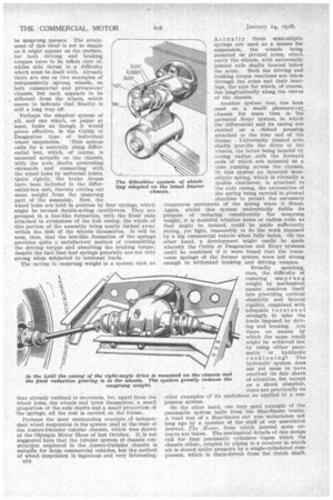
In passing, reference might be made with advantage to the various methods of anchoring springs of the semi-elliptic and cantilever types (with which most modern vehicles are equipped). Take the semi-elliptic spring, for 'example. The ends of the master leaves are, as a rule, looped to take a phosphor-bronze bush, through which a pin passes, one end of the spring being supported in a bracket attached to the frame, whilst the other end is similarly retained by a swinging shackle. As might be expected, the load on the bushes and pins is very high, and in a good many instances wear takes place fairly rapidly,
Recently a Silentbloc system of shackling the springs has conic into prominence. This system calls for a Cylinder of rubber to take the place of the normal bushing. for the eye of the spring, and which, when highly compressed between two tubes, forms a definite location for the shackle pin. Due to the elasticity of the rubber, however, the inner tube of the bush, which is in contact with the pin, can oscillate relatively to the outer tube. Thus sliding, and subse
fluently wear, is entirely removed, making lubrication quite unnecessary. .
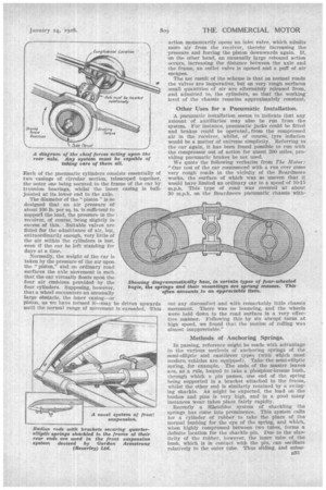
This system of utilizing the flexibility of rubber has been extended of late by Mr. Walter Lawton Adams (an engineer and inventor) as a means for evolving art entirely springiess suspension. Briefly, the idea calls for a rubber disc, having face serrations on each side; to be interposed between a stationary and inov-able plate; this latter movable plate carrying an extension in the form of an arm, at the extremity of which a road wheel is mounted. Thus the weight of the vehicle is taken through the three elements—the stationary and movable serrated members and the
rubber disc: A clamping bolt passes through the centre of..all three and forms merely a retaining device, the load being taken through the face serrations of the rubber disc. .
It is obvious, then, that so soon as a shock is received by the road wheel the end of the frame is forced upwards, which in turn strains the rubber disc torsionally. It has been found in practice that there is no
difficulty in obtaining adequate strength, and with the radius arm about 2 ft. in length an axle movement of 5 ins. or 6 ins, can easily be allowed.
Quite apart from the fat that the system works much as a cantilever system (in that practically all the spring itself is a " sprung" mass), there is a further advantage in that, when deflected, the rubber disc reacts and returns to its normal position but, as the disc cannot store up an appreciable amount of energy, it does wit throw the axle past the normal position, as in the case of a metal spring, consequently there is practically a dead-bea$ action.
The foregoing should give some idea of the potentialities of suspension systems, and whilst we make no pretence at having covered thoroughly all the possibilities it can at least be said that the systems as at present in use on the majority of commercial vehicles do not represent finality in design. As in the past," The 1iommer6ial Motor wishes to foster any new development that may in the long run help the industry.