


Petrol-Electric Transmission for Road Vehicles'
Page 3
Page 4
Page 5
Page 6
Page 7
Page 8
If you've noticed an error in this article please click here to report it so we can fix it.
In Comparison with Purely Mechanical Systems.
By Messrs. E. W. Hart and William P. Durtnall.
.Before proceeding to the subject which we are to discuss this evening, we wish to express our thanks to the Chairman, Vice-Chairman, and Committee for the honour they have done us in asking us to read, practically, the first paper on this most iiiteresting subject—petrol-electric power transmission. We had a certain amount of diffidence in accepting the invitation, owing to the fact that our latest chassis was not, at that time, completed, and on this, we felt sure, much of the interest would concentrate, because of our utilisation of, so far as road vehicles are concerned, a new class of electrical machinery, working with Pie alternating current. It was urged, however, that the work upon which we had been engaged was a subject which would, probably, bring forth a good discussion, and it is, therefore, with that object in view that we present this paper, rather than in the ordinary sense. When one considers the large number of buses, and other heavy vehicles, which are now on, and off, the streets of London only, and the noise from many of them, we think that a discussion on some method of improvement in transmission should not be lacking in interest.
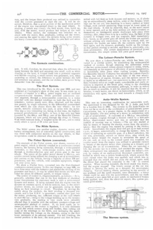
One of the most attractive subjects for the study of mechanical engineers is, possibly, the transmission of power and speed regulation, on motor vehicles, from various types of prime movers, and, since the first application, a very large number of ideas have been utilised, with more or less success. The subject is a very wide one, and, for thorough treatment, would require much more space and time than is covered by the particular object of this paper. Next to the engine, the power transmission is the most important thing about the vehicle, and bad design may make a considerable difference in the power obtained at the road wheels. It has been proved, by actual test, that fully one-half of the power developed by the engine is often lost in undue friction between the prime mover and the wheels. The system of transmission mostly used at the present time, is, that of metal gear wheels (in reality a group of three or more rotating levers) ; these provide not only a reduction of speed, but also a fairly proportionate increase of torque at the slower vehicle speeds, a thing which is absolutely necessary for motorbuses and heavy lorries, especially when climbing severe gradients; but, as all of you present here this evening will admit, this system is exceedingly noisy when the gear wheels are worn. It is not only an annoyance, but an eventual source of trouble and expense, for noise means wear, and the operating engineers of this Society will, we feel sure, agree with us that, if the gear box can be satisfactorily eliminated, it will be a welcome improvement, and, further, that the extra amount of work for the drivers is considerable in changing so often to meet the traffic conditions. It may often be noted, too, that drivers, rather than continually change gear, will run some considerable time with the clutch slipping, losing j.ower thereby,
and generating heat and wear on that piece of mechanism, whilst many breakdowns can be traced, too, to that cause alone. There are, of course, very many ingenious and scientific pieces of apparatus, such as the Hele-Shaw and other plate clutches, and various makes of epicyclic gears, which have gone very far in helping to produce a few fairly silent-running vehicles.
Electrical Power Transmission.
In dealing with this subject, we are taking up a matter with which we have had a certain amount of experience, and electrical power transmission, which has for its object the replacing of the mechanical speed-changing gear now in common use in connection with internal-combustion engines on road vehicles is, really, the matter for discussion. That otherwise ideal prime mover, the internal-combustion engine, has at least one fault ; it is wanting in elasticity, and, in order that it may be satisfactorily adopted, some sort of variable speed-changing device is necessary. The system usually employed, in petrol-electric systems, is that of a dynamo, coupled direct to the engine, which furnishes current for an electric motor, coupled mechanically to the road wheels, the vehicle being, actually, an electric car with, in place of the ordinary battery of accumulators usually employed, the engine and dynamo supplying the electrical power. True petrol-electric cars possess the inherent advantages of not being restricted to a given radius of action, of requiring no recharging, as in the purely electric systems, and of being able to run the same distance as an ordinary petrol and geared car.
Probably the earliest system employed was that of Patton (1890), in America, where he used electric tramcars, carrying a set of accumulators, and using a small petrol engine driving a dynamo to charge the battery ; the engine was always kept loaded and working at its full capacity, the accumulators supplying the current for the two electric motors. Such a system was complicated, and the efficiency was lOw, owing to most of the current having to go in and out of the battery.
The Dowsing System.
In this system, the petrol engine drove a shunt-wound dynamo, both engine and dynamo being "belted" to the road wheels and so arranged that the surplus power from the engine was converted into current for charging a set of accumulators. The connections were so arranged that, when the speed fell below normal, the dynamo became a motor, drawing current from the accumulators, and assisting the engine on inclines. This system was more efficient than that of Patton; furthermore, the dynamo was used to run as a motor, taking current from the accumulators to start the engine.
The Germain System.
The Germain petrol-electric system had very good points, insomuch that the field of the dynamo revolved round the arma
ture, and the torque there produced was utilised in connection with the current generated to start the car. It will be observed, therefcre, that a good portion of the mechanical power of the engine was transmitted direct to the road wheels. In :starting, a switch was closed ; the field would, then, build up, and, with the motor, would produce full torque at the road wheels. When started, the resistance was switched on in shunt with the motor, thus, gradually, cutting out the motor, and causing the speed to rise ; the dynamo being series wound, the heavy current then circulated within its own field and arrna ture. It will, therefore, be observed that, when the difference in speed between the field and armature was small, such as when running on the level, it formed itself into a powerful magnetic and flexible coupling, a small current was generated, and, when ascending an incline, the difference in speed between the field and armature was greater, and the car slower, more power being demanded from the engine.
The Hart System.
This was introduced by Mr. Hart, in the year 1903, and was exhibited at Cordingley's show of that year. It was made up as follows :—Coupled to a 40h.p. petrol engine was an enclosed compound-wound dynamo, which provided continuous current supplied, through a series-parallel controller, to a motor provided with two distinct windings on both the field and the armature; • various speeds were, thus, obtained, and the motor was geared, by single reduction, to the differential countershaft from which the side chains drove the rear wheels: for low speeds, metallic resistance was used, in series with the motor. This was a very interesting car, being, at that time, the highestpowered petrol-electric car built; in fact, it has only just been exceeded b the 45h.p. and 70h.p. cars of the Mercedes Electric Company, which are now going through the shops in Vienna. With fitted tonneau body, it weighed under 25 cwt., and it could easily attain a speed of 50 miles per hour.
The 1VIilde System.
The Mil& system was another engine, dynamo, motor, and battery arrangement, but of somewhat lighter construction, and was fitted with compound motors on the rear wheels, so that recuperation could be obtained when descending hills.
The Fisher System (converted).
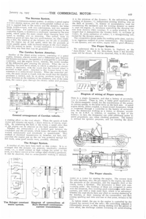
The example of the Fisher system, now shown, consists of a petrol engine, which is directly coupled to a continuous-current dynamo, the dynamo being connected, through a series-parallel controller, to two 711-np. series-wound motors, each coupled through a double-reduction spur and pinion gear to the rear wheels. The power of the petrol motor shown is 22b.h.p., any surplus current being utilised for charging a set of accumulators, also carried on the vehicle, having a capacity of about 150 ampere-heurs, and this vehicle, with complete equipment, weighs just over seven tons We show a Fischer lorry, converted into the Hart-Durtnall continuous current system. In this (see diagram on page 449), we have done away with the batteries and altered the winding of the generator and motor ; it may be added that means are here provided for about 12 different speeds, or torque values.
The system of control is, diagrammatically, as follows :—It is, generally, admitted that one or the best methods of electrical power transmission for stationary work is with a series-wound dynamo and motor. It being assumed that the engine runs the dynamo at constant speed, it will be noticed, that, in the switch position shown, no current can be generated, owing to there being no field windings in circuit. Therefore, by moving the switch along the contacts, the field winding is dropped inte circuit, and a low E.M.F. is generated; current then goes into the motor, producing, say, sufficient torque at the road wheels to start the car; owing to the voltage building up on the dynamo very gradually, the starting is very much more smoothly effected than is possible with the ordinary constant-voltage and series-parallel method of control. If, on level roads, an increase of speed on the motors is required, it is only necessary to pull the switch contact along still further, thus cutting out some of the windings on the fields, and increasing the speed. besides raising the voltage on the dynamo, owing to the then lower resistance of its external current. For hill climbing, the central position is the best ; the most power can then be trans. mitted eith full field on both dynamo and motors ; or, if climb. ing an extraordinarily steep incline, some of the dynamo windings can be cut out, this resulting in a heavy current at lower voltage, such current producing large torque at lower speed at the road wheels. It will be observed, that, as the main circuit is never opened, and as the field sections are short-circuited on themselves, no detrimental astatic discharges take place when running ; also, when there is to be a sudden stop, the field of the dynamo is bridged over, and the magnetic field immediately lost : hence, as all power goes off before the brakes are applied, without altering any connections, it will be noticed, that, immediately the brakes are taken off, the contacts open up the field again, and the dynamo, gradually, builds up the voltage, so that perfect starting is secured, and there is, practically, constant acceleration. For certain applications of electrical power transmission, this simple system will yield good service.
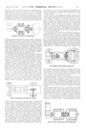
The Lohner-Porsche System.
We now show a Lohner-Porsche car, which has been converted to a similar system, by eliminating the series-parallel method of control, though retaining the differential action of the two series-wound motors always coupled in series, which, unfortunately at the expense of efficiency of power transmission, so beautifully takes place when turning corners. Recently, the Mercedes Electric Company has adopted the Lohner-Porsche system, but with the motors in the hubs of the rear wheels. This disposition of engine, dynamo, and two motors cannot be accepted as an efficient one ; our experience is, that, after two or three hundred miles on rough roads, considerable and costly attention is required at the brush gear, owing to the chattering of the brushes on the commutator, although, in order to reduce this as much as possible, it will be observed that the 12 sets of brushes, in each motor, arc thrust on horizontally, which, as all electricians will agree, dots not tend, towards a cheaply-made machine.
Astle-Wallis System.
This was an interesting combination for automobile work. We understand it was designed by Mr. M. J. Astle, and built by a London firm in 1901. The novelty in the Astle-Wallis car does not lie so much in the combination of petrol-electric power tiansmission, but, in a greater degree, in the employment of a single dynamo, this also acting as a motor in conjunction with a set of accumulators. It consisted of a 10b.h.p. two-cylinder petrol engine, coupled through a friction clutch to a four-polo 21).h.p. shunt-wound motor, and was so arranged that the method of running was as follows :—The car was started at first by means of running the electric motor from the accumulators; then the engine was started by putting in the friction clutch. Immediately the engine fired and got up to half normal np.m., it began, automatically, to charge the battery; then, by means of operating an epiryclic gear, of a 3-to-1 reduction, the car was, practically, started on direct drive, after which the electric motor helped the engine to accelerate the speed of the car, and, as soon as the normal speed was acquired, the surplus power from the engine was utilised to generate current by means of the electric motor (then running as a dynamo and charging the set of accumulators). When the car ascended a hill, the dynamo ran as a motor, and assisted the engine. The whole arrangement was automatic, and under the driver's control, by means ofan eight-position 15-contact controller, embodied in which was a carbon break-switch, which severed the main circuit when the brake was applied, and which was so arranged that the switch did not close the circuit again until the driver had placed the controller in the "off" or neutral position. When running downhill, the front clutch was drawn, and the engine stopped. The kinetic energy of the car was utilised in driving the motor as a dynamo, for accumulator charging. Various braking effects, according to the severity of any gradient and the speed required, were obtainable: a heavy charge could be sent into the accumulators, and the car made to descend a very steep hill at slow speed, no mechanical brakes being applied, and, from the electrical aspect, this system promised good results. The Stevens System.
This is a continuous-current system ; it utilises a petrol engine and two electric motors, and the series-parallel method of control is applied both to the motors and the dynamo, the latter being double-wound, with two commutators, and two separate field windings. For prevention of sparking and burning at the controller fingers, a resistance is employed, operated by the foot pedal, which opens the main circuit when changing from one speed to another, and on reversing. This system, from an electrical point of view, has very good features, as, when climbing a hill, the winding of the dynamo can be put in parallel, and the engine run at full speed, while the car proceeds at about quarter speed, with increased torque at the road wheels, with the motors in series. Forced ventilation is introduced to take away any heat that may be generated.
The Carolan System (America).
Another of the direct acting systems, consisting of a petrol engine, dynamo, fgectric motor, and a differential gear between the dynamo and motor ; its operation is arranged for a nine-finger controller, and the engine drives, directly, the centre member of the differential gear carrying the pinions. When the car is standing, the back bevel wheel, to which is attached an electric motor, is stationary, with the result that the forward wheel is revolved at high speed. Attached to this forward bevel is the armature of a series-wound dynamo. When the controller permits, the main circuit is closed, with the result that the dynamo generates a current, and, by so doing, produces torque in the same direction as the rotation of the armature, and, at the same time, the current goes through the electric motor and produces a starting effort on the road wheels. When the speeds of both motor and dynamo are equal, a ditect drive is, of course, available. By weakening the field of the motor, a speed above that of the engine can be attained on the back propeller shaft. Whether the interposition of a toothed gear between the crankshaft and the armature, which forms the engine flywheel, worked satisfactorily and noiselessly is questionable. This method of electrical transmission is, however, not bad, and, provided the engine put on the car was powerful enough for hill work, some good results were, possibly, obtained.
The Krieger System.
A number of cars have been built on this system. It is so arranged that the dynamo can generate, practically, constant watts, i.e., a small current at high voltage for speed on the level, or a heavy current at low voltage when climbing gradients. It will be observed, that no series-parallel working is utilised.
A is the armature of the dynamo; B, the self-exciting shunt Winding of dynamo; C, independent exciting winding, also on the field of dynamo; D, battery of accumulators, used for maintaining the excitation and for running dynamo as motor to start the engine; E, resistance controlling the charging current from dynamo when running ; F, a series winding, so arranged that it demagnetises the dynamo field ; G, armature of motor ; H, series excitation of motor ; I, a demagnetising coil, excited by the dynamo armature.
The connections shown make the working quite clear, and this is an ingenious method of power transmission. The limitation :o one dynamo, arid one motor, argues well for good efficiency.
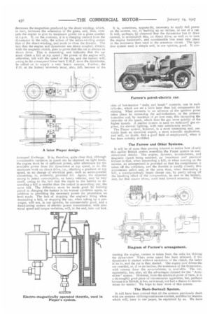
The Pieper System.
We understand this is to be known, in England, as the "Auto-Mixte," but, with Dr. Hele-Shaw, hope a less horrible name will be chosen. It will be observed, that, in this system,
there is a single dynamotor, and that a battery of accumulators is retained. There is, also, a fairly good application of the electro-magnetic clutch, for the transmission of the power, at various speeds, to the bevel drive on the back axle. A petrol engine drives, direct coupled, a shunt-wound dynamotor, which is connected through a controller to the battery of accumulators, the dynamotor working as a motor, or dynamo, according as its E.M.F. is inferior, or superior, to that of the battery ; in fact, the dynamotor can yield additional power to assist propulsion, say, when climbing gradients. The battery is utilised for ignition purposes, and for running the dyna
motor as a motor for starting the engine. The current from the cells regulates, also, the gas supply to the engine, for which the armature of the dynamotor, and the magnetic field of the clutch, forms a flywheel. The dynamotor is fitted with commutating poles: the windings of these are connected in series with the armature, thus ensuring good commutation with heavy currents, and with a weak main field, which is an advantage. Whether the road shocks have any effect in causing chattering at the brushes, or their jumping off the commutator, and thus causing sparking and wear and tear at that point, remains to be seen.
As before stated, the gas to the engine is controlled by the demand for current from the cells ; the controlling solenoid is differentially wound, so that, during starting and the period of extra effort, the discharge current traversing its series-winding
decreases the magnetism produced by the shunt winding, which, in turn, increases the admission of the gases, and, thus, compels the engine to give its maximum power for a given number of r.p.m. If, on the contrary, it is a charging current from the dynamotor to the cells, the action of the series-winding assists that of the shunt-winding, and tends to close the throttle. The fact that the engine and dynamotor are direct coupled, always, with the magnetic clutch, goes to prove that the car is always on direct drive. This is interesting, and indicates that the car must climb a hill at top speed ; the power of the engine win, otherwise, fall with the speed of the car, and the battery will, owing to the consequent lower-back E.M.F. from the dynamotor, be called on to supply a very heavy current. Further, the P.D. at the battery terminals must, also, fall, because of the increased discharge. It is, therefore, quite clear that, although considerable variation in speed can be obtained on light loads, the engine must be of sufficient power, after allowance for the available power from the dynamotor at top speed, to do the maximum work on direct drive, i.e., climbing a gradient at top speed, as no change of electrical gear, such as series-parallel connecting, is, evidently, provided for. Again, the expected saving in petrol consumption, on heavy vehicles, may be very small, owing to the fact that the input to the battery in descending a hill is smaller than the output in ascending, say, the same hill. The difference must be made good by burning petrol in charging the battery to its normal condition again, in addition to providing the necessary power for propulsion on level roads. The fact of stopping the engine's firing when descending a hill, or stopping the car, when taking up a passenger, will not, in our opin'on, be commercially good, and a direct-acting system of electric power transmission, with electrical speed and torque variafon, will, in the end, turn out best. It is, sometimes, apparently, necessary to apply full power on the reverse, say, in backing up an incline, or out of a rut. It will, perhaps, be observed that the dynamotor has to draw current, to accomplish this, on direct drive, as well as to turn the engine backwards, and considerable loss must take place in the resistance then used in the armature circuit. The ignition system used is simple and, in our opinion, good. It con sists of low-tension "make and break" contacts, one in each cylinder, which are set a little later than full compression for starting. What amounts to an advance of the ignition point takes place by increasing the self-induction, in the primary induction coil, by insertion of an iron core, this increasing the intensity of the spark, which fires the gas more quickly at the higher speeds. A similar system is used on stationar}r gas engines, for electric lighting, with very satisfactory results.
The Pieper system, however, is a most interesting and, certainly from an electrical aspect, a most scientific application, and will, no doubt, find a good field of employment, when it has been suitably modified.
The Farrow and Other Systems.
It will be of more than passing interest to notice how closely this earlier British system resembles the Pieper system in constructional details. The engine, dynamo, accumulators, and magnetic clutch being retained, an important and practical feature is that, when descending a hill, or when running on the reverse, an arrangement is provided so that the compression is taken off the cylinders, and the throttle is totally eosed ; this economises petrol and, at the same time, when descending a hill, a correspondingly larger charge can, by partly taking off the breaking effect of the compression, be sent to the battery, and, for that reason alone, must tend toward economy. When
starting the engine, current is taken from the cells for driving the dynamotor. When some speed has been attained, if the dynamotor is started without excitation of the clutch, the latter is let in, and the car is then started. The engine now drives the car unaided, or, if on an incline, the assistance of the dynamotor, with current from the accumulators, is available. The car, apparently, has, also, all the advantages claimed for the "Automixte" system. However, from the electrical point of view, it is a thoroughly good piece of transmission apparatus, but, perhaps bacause it is British, it has, as is usual, not had a chance to demonstrate its merits ! We hope to hear more of this system.
The Hart-Durtnall System.
It will have been noticed that all the systems previously dealt with are systems utilising continuous current, and this for reasons which will, later in Our paper; be explained by us. We have brought out a system of power transmission in which polyphase, alternating-current apparatus is adopted. One of the principal things which led us in that direction was that considerable trouble and unreliability was experienced by us when transmitting high power with cbritinuous-current apparatus. Electrical engineers, generally, will admit that the polyphase, alternating-current, induction motor has become very popular recently for stationary work, mainly owing to its powerful starting torque and to its freedom from commutator and brush troubles. A
burnt-out armature, the perpetual source of dread in continuouscurrent dynamos and motors, is practically unknown in the polyphase, alternating-current, induction type, even when put to most severe service, and its depreciation, under fair conditions, is as low as any class of rotating machinery, whilst its simple and substantial construction is one of the chief advantages, resulting in low cost of maintenance and attendance. Observe, too, how it differs from the single-phase, alternating-current induction motor, which has the disadvantage that it is unable to start against load. The single-phase type is, also, less flexible as regards speed, but, in other respects, the single-phase type is similar to the polyphase, alternating-current, induction motor.
For the benefit of those gentlemen who, possibly, may not have had experience with polyphase, alternating-current, induction motors, we will briefly give a simple explanation of its construction and working. A polyphase, alternating-current, induction motor consists essentially of two parts, the stationary and the revolving. In most modern motors, the stationary part, or "stator," contains the coils through which the current passes ; a polyphase current, flowing through the " stator " windings, produces a rotating magnetic field, which field acts upon the revolving part, or "rotor," and induces in it currant which magnetises it, so that the "rotor" becomes practically an electromagnet, but is only excited, or maintained in that state, by the induced current from the surrounding "stator." That is the reason why such a motor is generally referred to as an " induction " motor. When running without load, the speed of the motor is very nearly that of the rotating field produced in the " stator," or nearly synchronous ; then, there is a very small current induced in the "rotor" winding. The magnetic pull of this small current on the rotating field produces a feeble torque, and the current consumption by the "stator" is, then, only the magnetising current required to overcome the mechanical and magnetic friction of the motor. When the load is applied, the speed of the motor falls by a small percentage, increasing the voltage and also the induced current in the "rotor," and a powerful torque is produced by the pull of this increased current in the "rotor." The difference between the speed of the '` rotor" and that of the revolving field in the " stator " is called the "slip." and this " slip" is proportionate, to a certain extent, to the resistance of the "rotor" windings. It will, thus, be seen that, the greater the load put on an induction motor, the greater will be the "slip ;" abso:ute synchronous speed is never obtained in an induction motor, for, as seen, there is, even at no load speeds, a certain amount of " s'ip " required to generate sufficient current to overcome the light-load running losses. This fall of speed, or "slip," in a wel-designed motor will, generally, vary from about 1 per cent. at light load to about 10 to 15 per cent. It has been stated that the induction motor is not flexible in respect to regulation of speed, but there are several methods of obtaining a variation of speed with polyphase, induction motors. One method is the insertion of a resistance in the "rotor" cir cuit, but that wastes power, as do all motors using resistance in their armature circuits. Another method is the variation of the voltage of the alternating current to the "stator," thus causing more or less slip. A third method is by changing the number of poles of the " stator," and so arranging them that, although the periodicity of the supply current remains constant, the motor can turn at, say, one-quarter, one-half, or full speed. This result is very similar in action to, though, in fact, very much snore flexible than, an ordinary set of change-speed gears. You will possibly observe that the main current, at full pressure, simply passes through the " stator " windings, which are quite enclosed, the current not traversing any exposed part such as a commutator, brushes, etc., and, as these windings are stationary, there is no danger of mechanical injury. The insulation of the " stator " can be made very secure, as it is not rotated, and can, therefcire, stand a varying voltage better than would be permissible with a continuous-current motor.
The most important item in favour of the induction motor is the revolving part, or "rotor ;" in this, only low voltages are generated, and, consequently, very little insulation is required. In fact, polyphase motors are working well without insulation in the slots carrying the " rotor " bar windings. The " rotor " can, thus, be very much more strongly and mechanically built than a continuous-current motor, with its revolving armature, through which the full-pressure current has to pass, and in which case, for high voltages, the windings have to be fine wire, expensively insulated and liable to burn out. The continuous-current motor requires a commutator, to convert the current into an alternating one as it enters the windings of the armature; this
fact necessitates the use of brushes for a rubbing contact, and these require a deal of attention from time to time for trimming and adjustment, whilst the commutator occasionally requires turning up, and this pretty often if there is any sparking, which is very liable to occur, especially if the motors have to be cut down in weight, as have all automobile motors.
l'olyphase induction motors do not require any commutator, and are free from that very expensive and, at the best, very undesirable part, which is absolutely essential to the continuouscurrent motor, a fact of which some of the operating engineers would, if they had, say, with 100 buses, say, 300 commutators, and, say, 1,200 brushes to keep in good daily order, we feel convinced, be aware. They would then not only have their usual troubles, but would become very quickly acquainted with brush troubles.
With polyphase induction motors, and especially if fitted with short-circuited "rotofs," there is absolutely no chance of spark. ing. This point will be appreciated by Insurance Companies, and by Scotland Yard, in respect of motor vehicles carrying inflammable materials such as petrol. The dimensions and weights are smaller, power for power, than those of continuous-current motors, and, owing to their simplicity, polyphase induction motors are more suitable to be left in the hands of ordinary drivers, or of unskilled workmen. It is an important fact that, if a polyphase induction motor is driven independently, above synchronism, it becomes a generator and an absorber of mechanical power ; the effect of this feature is emphasised by us later. The, important part this quality will take in the economical running of public-service vehicles is only one of the many advantages of this method of transmission, and one which will become fully apparent when more trials have been completed.
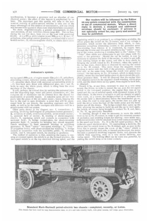
We show, diagrammatically, a general arrangement, in plan and elevation., of our motorbus chassis (page 455). The car has, during the last few days, been rim on the road with gratifying results. A is a 40h,p. petrol engine (speed 800r.p.m.); B, fan ; C, polyphase, alternating-current generator, combined with a serieswound exciter ; D, electro-magnetic clutch, to obtain direct drive
on top speed (800r.p.m. of engine equals I2m.p.h4 ;F., polyphase, alternating-ciirrent, induction motbr, coupled direct by means of — F, propeller shaft, fitted with universal compensating joints to live back aide, fitted with differential gear, etc. ; and II, bolts to carry the whole plant, which is slung from the cross members of the chassis.
It will, perhaps, be noticed that, by undoing the universal joint and the supporting lugs, water and petrol connections, etc., the complete set of machinery can be lowered from the chassis for examination or possible repairs. A complete spare set can very easily take the place of the set under repair ; hence, keeping the bus on the road to earn dividends—a point that wilt be appreciated both by our friends, the operating engineers and their staffs, as well as by the traffic managers and directors—will be a simple matter with our system.
Other parts shown in the diagram are: I, connections ; J, exciting, revolving field-magnet of polyphase-current generator ;
K, armature of small, continuous-current, series-wound exciter ; L, sectional field of exciter ; M, winding of electro-magnetic clutch ; N, regulating switch and contacts in connection with sectional field ; 0, bridge contact-piece, for short-circuiting generator field; P, contacts for bringing into circuit magnetic clutch windings ; Q, fixed armature winding in polyphase generator ; R, fixed " stator " two-speed windings ; 5, " rotor " of polyphase motor, with short-circuited bar winding ; T, bridge contact in connection with the foot-brake pedal ; U, reversing switch ; and V, two-speed switch, for starting on gradients.
The method of operation is that, assuming the engine is running at constant speed, the switch is on the forward position, the two-speed switch is on the top electrical driving speed, and the
regulating switch is on position 1, no voltage being available, the driver places the switch on No. 2 contact, and a !Ow voltage is generated, which excites the alternator field, which, in turn, generates polyphase alternating current in the generator armature-winding, from whence it is conducted, by copper bars, through the reverse and two-speed switches to the " stator" winding in the motor, producing a rotating field in the " stator ;" the " rotor " then starts and endeavours to get into phase with the speed of the generator.Should the car be loaded, it may be necessary to increase the field of the exciter, in order to get sufficient starting torque at the -motor, and this is done easily by bringing the switch round to No. 9 contact ; when the speed of the car has risen, direct drive is obtained by moving the switch on to No, 10 contact. This move drops the magnetic clutch winding in series with the field of the generator, weakening this field and, at the same time, brings the clutch over gently into contact ; the last move, to No. 11 contact, which is made immediately, causes the insulated bridge-piece to short-circuit the polyphase generator field. it will be observed that the exciter then only supplies current to the magnetic clutch winding, which grips solid, and the direct drive on top speed, from engine to back axle, is obtained.
Should it be, at any time, necessary to stop on a very steep ascent, the driver, in order to restart the car, puts his two-speed switch in the low-speed position ; the engine then runs at top speed and the car at reduced speed, with increased torque at the road wheels. In the event of occasion to pull up sharply at speed, cross roads, or a corner, the bridge-contact is so arranged that the exciter field is short-circuited before the band-brakes go on, and, when the road is clear again, the exciter does net pick up until the driver takes his foot off the brake pedal and the bandbrakes are off the drums. The bridge-contact then opens up the field, allowing the exciter to build up and the car to start again, the switch, of course, being brought to contact No. 9, and, later, to No. 11, as, previously described. In starting, though it may be necessary to move the switch lever as far as No. 9 contact, in order to get the necessary amount of excitation and resulting torque for starting ; once under way, sufficient excitation will be obtained from lower contacts according to the speed and levels. No. 11 is the full speed position ; No.
is the top speed electrical drive. On approaching a declivity, the driver puts his switch lever on No. 9 contact, and, as soon as the force due to gravity causes the r.p.m. of the " rotor," which is coupled direct to the hack axle, to exceed synchronism, the motor becomes a powerful revolving magnetic brake, and prevents the vehicle from acquiring, even on a very severe declivity, any undue speed. The braking effect can be made less powerful, by putting the switch lever on to lower contacts.