


Side-slip and Skid Prevention.
Page 16
If you've noticed an error in this article please click here to report it so we can fix it.
First Notice of the Devices Entered for the A.C.G.B.I. Trials.
(Continued from page 443.)
The device of Mr. P. G. Hedges, of t, Fourth Avenue, Harrow Road, W., consists of a series of wedge-shaped steel shoes (shown at B in the accompanying illustration (Fig. 1.5). These are suspended by flat steel springs (A), suitably bent to follow the contour of :he outer part of the tire, and secured, by in,:ans of set screws, to the felly of
the wheel. The seclional view of the tire clearly sho%‘s the dkposition of these shoes, the points (c and d) being held, when the wheel is running normally, in the position 1.11owl. Should a side-slip occur, the tire would mount the shoes, successively, and the weight of the vehicle, bearing upon each shoe, would cause it to grip the road surface securely.
The following short description is of the apparatus entered by Mr. T. Horace Reeves, of 2, Penywern Road, S.W. ;---A channelled rim is arranged on the wheel, and, within it, a number of spring boxes, oblong in shape, are placed. These boxes are open al their outer ends, which are finished with inturned flanges_ A semi-circular stud, or block of wood, is arranged to project through the opening of the box, and is fastened to an iron backing plate, which moves freely in the box. Two springs are placed between the hacking plate and the closed end of the box. These force the wood block forward into contact with the retaining flange, at the outer end of the box. A large number of these boxes are fitted transversely in a channelled rim, and a slab of impure emery stone is fastened on the top of each block, in order to enable the trt.ad to obtain a firm grip of the road surface, and so secure immunity from side-slip or skidding. Our illustration (Fig. 16) shows the method of arranging this device. The invention of Mr. E. Whiting, of Station Parade, Queen's Road, Peckham, S.F., is illustrated in Fig. t7. From this it will be seen that an oval roller, some 17 inches by 12 inches, which bears upon the road, is loosely contained within a cage secured to the under part of the carThis roller, when the vehicle is moving normally, runs easily over the road. Should sideslip occur, however, the roller takes up the position shown by the dotted" lines, and it will, then, become a rolling strut, interposed between the road and a suitable hearing surface provided on the under side of the car. A lead ball runs in the interior of the oval roller, in order to add to its steadiness and render it more sensitive in its action.
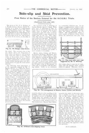
Messrs. Jones, Cotton and Brierly, of Palatine Buildings, Blackpool, have entered a device which shows a somewhat different method of dealing with the question of side-slip. This is illustrated in Fig. t8, which is self-explanatory, and it will be seen, clearly, that the pads, which are composed of a number of rollers, drop on the ground, on either side, in sympathy with the steering wheels. Little, or no, resistance would be offered to the travelling of the omnibus, whilst some soo square inches of surface contact is obtained, which would resist any attempt of the rear portion of the vehicle to move laterally.
The device of Mr. William Lowry, of The Laburnums, Bourne End, Bucks, is a somewhat elaborate one. In hi design, a supplementary wheel is used, which, however, is not intended to grip the road surface with the object of stopping the lateral movement of the vehicle. The supplementary wheel is. used, merely, to operate a lever, which brings the mechanism into play, and
this it does when it runs out of alignment with the driving wheel, behind which it is placed. The lever, which is
moved by the wheel, in this event, operates a number of cams on the inner side of the wheel, which control a series of oblong, segmental shoes_ These lie, normally, between the twintires of the wheel, but, when brought into action, by the deviation of the supplementary wheel, they rise out of the groove between the tires, and, turning, take a position diagonally across the treads, giving the tire something of the appearance of the stroked wheel which has been used in several examples of heavy motors. When the side-slip has ceased, and the supplementary wheel runs, again, in alignment with the driving wheel, the catches are released by the lever, and the shoes spring back again into place between the two treads of the tire. It will be seen, thus, that side-slip must first occur before the apparatus comes into operation.