


Volvo Develop Blown Oil Engine
Page 28
Page 29
If you've noticed an error in this article please click here to report it so we can fix it.
A Short Test of a chassis Fitted with Blown Engine Shows its Value : Automatic Transmission for Bus Chassis in Production
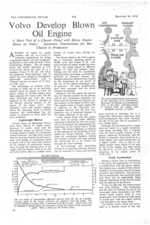
ABLOWN oil engine for goods vehicles and an automatic hydraulic transmission for fitting to passenger chassis are now in quantity production at the works of A.B. Volvo, Gothenburg, Sweden. Theoil engine, which was briefly described in The Coinmercial Motor for July 16, is a standard Volvo D 96 AL 150 b.h.p. six-cylindered direct-injection unit to which has been added an Eberspacher lightweight turbo-blower, with a resultant increase in power of 35 b.h.p. at 2,200 r.p.m.
The advantages of exhaust turboblowing to make use of an otherwise wasted source of energy to boost the power output of existing engines have been apparent for many years, but the main drawback has been the slow response of the blower to changes of the throttle opening because of the inertia of the heavy rotor. For stationary units and marine engines, where the operating speed is usually constant, this disadvantage has not arisen, so progress in those fields has been profitable.
Lightweight Blower Several makes of lightweight blower have been offered to engine manufacturers in recent years and the Eberspacher design, as used by Volvo, is being adopted widely by Continental vehicle concerns. The light rotor ensures that the time-lag between throttle movement and change of compressor speed is small, and at the same time, because of the absence of mechanical connections between the rotating parts of the engine and the blower, there is no risk of broken drives due to a sudden trans
ference of torque when driving the blower.
The blower fitted to the Volvo engine has a maximum operating speed of 38,000 r.p.m. and weighs 37 .1b. The total increase of engine weight has been 55 lb., this being caused by different designs of inlet and exhaust manifolding and the need for mechanical injection-pump governing. A mechanical governor is necessary because the changed induction characteristics caused by the compressor do not permit of the use of the lighter pneumatic type of governor. No other modifications have been necessary and the pump setting is unchanged.
Research with the engine has proved that the thermal stresses on the pistons and in the combustion chambers are lower and the internal soot deposits are less because of the higher air-fuel ratio. This should result in longer engine life in addition to the improved performance derived, and the fuel consumption rate is improved because of the higher efficiency of the unit.
Volvo chassis fitted with this engine have been in service under differing operating conditions for over two years, and at the moment the approximate life expectancy of the blower unit is 32,000 miles. The blower efficiency is reduced at this mileage by the formation of soot within the blower housing. This soot clogs the ventilating channels, raising the internal pressure and thus causing the lubricating oil to be forced out through the rotor bearings. • • A part-exchange and reservicing, scheme is in operation whereby blowers, can be returned to Volvo and serviced' units received in exchange, but it is hoped that when more experience with turbo-compressors 'has been obtained. the life of the unit will be extended to over 60,000 miles.
Although the increased power output does not result in a higher maximum road speed, travelling time is reduced' with the blown engine because of the greatly improved acceleration and the ability to negotiate steep gradients in a much higher gear and consequently at a higher speed. . This is , due to the higher torque value, which,. in the case' of. the 'Volvci engine, has been raised, by. 100 lb.-ft. to 529 lb.-ft., this value, occurring . at in '• engine spded of 1,400 r.p.m.
• Good. Acceleration During a.recent visit to Gothenburg' I was 'given the opportunity of driving a -vehicle fitted with the blown engine. The vehicle was a standard Titan chassis loaded to 14 tons gross, and the Increase of power was noticeable. The acceleration in second-gear Was extremely good and there Was no apPreciable delay. between depression of the throttle pedal and the take-up of the blower.
It was on hills that the improvement was most striking. The compressor has the effect of making the use of the lower-gear ratios unnecessary and hills which would require third or even second gear were climbed at high speed in fourth gear with the engine pulling well throughout the speed range.
The blower whine, which was noticeable to a limited extent in the cab,
especially at high speeds, is not in any way obtrusive and is not pronounced from outside the vehicle. There should be no objection on noise grounds to the use of such a unit in a passenger vehicle and many advantages to be gained by way of faster running schedules.
The hydraulic transmission, which has been developed for use with the D%AL unblown engine, has been fitted to a number of Volvo city buses in operation in Gothenburg, and the Gothenburg Tramways Department have placed further orders following the proved advantage of the system.
The transmission consists principally of a hydraulic torque-converter, a multiple-plate clutch, two epicyclic gear trains and a control unit, known as the auto-pilot. High transmission efficiency at low speeds is achieved by the use of a double-rotation, two-stage turbine torque converter.
Opposite Rotation
With this type of.converter the centre Set of blades, which are normally static, rotate in the opposite direction to the normal turbines, thus working as a third turbine and increasing the torque multiplication to give a stall-torque ratio of 8-9 to 1.
When starting from rest at full throttle the drive is taken through the converter which is acting with double rotation. At a road speed of just over Ii mph. the guide wheel of the centre turbine is locked stationary (single rotation) and the converter works conventionally until the road speed is 25 m.p.h., when it is disengaged and the power is transmitted through the directdrive clutch.
Of the two sets of gearing, one train is used to transmit the power delivered b.y the guide wheel of the centre turbine when in the double-rotation range, and the other train can be mechanically engaged to give a reverse ratio. Two brakebands take the reaction torque in the doubleand single-rotation ranges respectively.
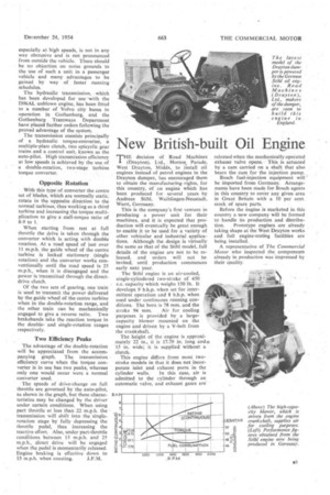
Two Efficiency Peaks
The advantage of the double-rotation will be appreciated from the accompanying graph. The transmission efficiency curve when the torque converter is in use has two peaks, whereas only one would occur were a normal converter used.
The speeds of drive-change on full throttle are governed by the auto-pilot, as shown in the graph, but these characteristics may be changed by the driver under certain conditions. When using part throttle at less than 22 m.p.h. the ' transmission will shift into the singlerotation stage by fully depressing the throttle pedal, thus increasing the tractive effort. Also, under part-throttle conditions between 13 m.p.h. and 25 m.p.h., direct drive will be engaged when the pedal is momentarily released. Engine braking is effective down to 13 m.p.h. when coasting. J.F.M.