


Patents Completed.
Page 20
If you've noticed an error in this article please click here to report it so we can fix it.
Complete specification of the following patents will be sent to any address in the United Kingdom upon receipt of eightpence per copy at Sales Branch, Patent Office, Holborn, W.C.
NON-SKID DEVICE.—Garrett.---?o. 12,579, dated 11th June, 1908.—This device is attached to the axle of the vehicle and comprises two brackets (b) bolted to the axle (a) and rigidly connected together by a cross bar (c/). Pivoted in elongated holes (g2), which are formed in the brackets (b), are levers (g) he long arms of which carry small wheels (h) connected by means of a spiral spring 11r) which tends to maintain them in a vertical position, The wheels (h) are bevelled and are, provided with a nariow tyre (hl )which is normally in contact with the road. When hiding occurs the lever (g) will turn on its pivot thus bringing the full face of one of the wheels (in into contact with the ground, and the arm (g11 of the lever (g) will bear against the underside of the bracket (b) and will thus jam the wheel (la) against the road, In this way skid. ding is prevented.
LUBRICATION SYSTEM.—Poppe.— No. 27,074, dated 7th December, 1907.— In order to prevent the collection of oil at one end of the crank chamber when the car is on a gradient, partitions (A) are provided dividing the chamber up into four compartments (A). Each of these compartments are provided with a trough or channel (D) inclined to the front of the vehicle, such inclination being greater than any gradient likely to be met on the road. Each channel (D) communicates at its lower end through an open. ing (G) with the next compartment, and, consequently, oil thrown up by the splashing of the crank in one compartment collects in this channel and runs down through the opening (G) into the next compartment. The channel (D) in
the front compartment communicates in a similar manner with a pocket or chamber (Ei which in turn communicates by a pipe with the rearmost compartment. In this manner automatic circulation of the oil is obtained without the necessity of special moving parts whilst a correct amount of oil is retained in each compartment.
MOTOR TRACTOR.—Marshall.—No. 25,629, dated 19th November, 1907.—This invention relates to motor tractors for agricultural purposes which may be used for hauling, ploughing, etc., and also, when stationary, for driving by belt a thrashing or similar machine. The motor
(a) is mounted midway of the chassis and ..-:rives the shaft (b), which in turn drives through suitable change-speed gear a bevel wheel (as) on a transversely arranged shaft (u). The shaft In) drives, by means of a pinion (a), the gear wheel fp) and the ff erent i al 'gear (not shown on the rear road wheels). Mounted on a countershaft (ill of the change-speed gear is a bevel pinion (r) having a jaw clutch formed on its face engaging with a sliding clutch (s). The bevel pinion (r) engages with the bevel wheel !I) mounted on a vertical shaft (u) on which is also mounted a pinion (v). This pinion (v) engages with an internal toothed wheel (w) attached to the winding drum (x) erderneath the frame of the tractor. Mounted on the shaft (d) of the changespeed gear is a bevel wheel (z) engaging with a corresponding wheel WI on a shaft 1x1). This shaft carries a pulley (yll suitable for driving by belt a thrashing or similar machine.
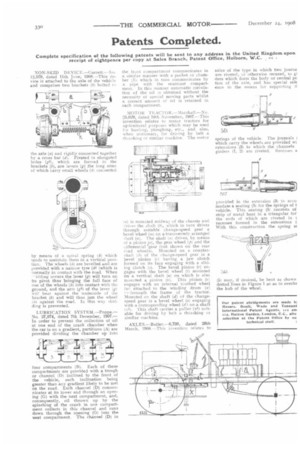
AXLES.—Butler.-6,730, dated 26th Match, 190B.—This invention relates to axles of the type in which two journa are riveted, or otherwise secured, to gi ders which form the body or central pc tion of the axle, and has special refe ence to the means for supporting tl springs of the vehicle. The journals I which carry the wheels are provided wi extensions (3) to which the channels girders (1, 21 are riveted. Recesses a provided in the extension (3) to acco modate a seating (5) for the springs of t vehicle. This seating (5) consists of strip of metal bent in a triangular for the ends of which are riveted in t recesses formed in the extensions ( With this construction the spring st (5) may, if desired, be bent as shown dotted lines in Figure 1 so as to overlie the hub of the wheel.