


Patents Completed.
Page 20
If you've noticed an error in this article please click here to report it so we can fix it.
Piston Construction. Operating Valve Tappets. Carburetter Design. Lubricating Laminated Springs.
Copies of complete specifications of the patents published on this page can be obtained from the Sales Branch, Patent Office, Holborn, W.C„ at the cost of sixpence for each specification, • G. R. Eden-, No. 15,069, dated 25th October, 1915.—This specification describes various con.structions of piston 'iu which provision is made for allowing free expansion of the head. In the construction illustrated in the accompanying drawing, the cylindrical body-of the piston is made in one piece, and the upper edge of the walls is bevelled inwards. The piston head is made somewhat smaller in diameter and similarly bevelled. It is attached to the body by a central spindle which also carries the gudgeon pin. -The spindle is mounted in a chamber with a compression spring between it and the end wall of the chamber. When the piston head gets heated, it expands radially and rides up on the bevel. The spindle is therefore drawn into the chamber, compressing the spring and locking itself b3.7 a shoulder engaging the end wall of the chamber. The spring keeps the head and the body in -close contact with one another even when the engine is cold.
P. H. E. MILLER, and E. TETLOW., No, 100,827, dated 7th May, 1915.—This invention provides a valve gear in which the valves are operated by a camshaft rotating at engine • speed. Very rapid opening and closing is thereby obtained, and the volumetric efficiency of the valves is increased. The accompanying drawing shows the mechanism for one valve. The camshaft. at the bottom radiates at engine speed. Above it there are mounted tappet guides which rotate on a shaft driven at one-quarter of the engine speed, and tappets in these guides are so disposed that when in contact with the cam they are also in contact with the valve stem at the top. Resilient guides on the side of the casing ensure the valve tappets being brought into the correct position for engaging • with the cams. The valves are thereby lifted by cams operating at engine speed through tappet members which are only. brought into operative position on each alternative stroke of the engine. 0. BAILIN, No. 12,161, dated 16th May, 1914.—This inven. tion relates to carburettors of the type having two main jets in the induction pipe, One of them being arranged to be put out of action automatically at high engine. speeds. Various constructions are described in the specification, and one of them is illustrated in the accompanying drawing. The two main jets are arranged to enter the choke tube horizontally, and one of them is connected to the float-feedchamber by--a. pipe which is also open to atmosphere. The arrangement is such that at high engine speeds this jet does not supply fuel, but, air is drawn through it instead. The main feature of the-invention consists in the provision of a third jet which is supplied directly from the float feed chamber without any restriction in its passage. The choke. tube for this jet opens into the throttle casing and the throttle is so arranged that the auxiliary jet is shut off for all open positions of the throttle, but is open through a small orifice when the throttle is closed. This arrangement is shown in the detailed view of the throttle.
A. MYERS and F. R. BAKER, No. 7717, dated 25th May.
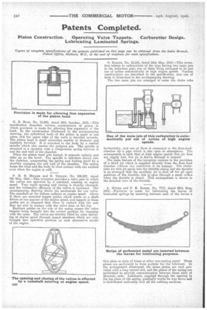
• 1915.—Provision is made for lubricating the leaves of laminated springs by inserting between each of the leaves a thin plate or strip of brass or other non rusting metal. These !plates are perforated to form pockets for the lubricant. In the arrangement illustrated, the brass plates are each provided with a long central slot, and the plates of the spring are perforated to provide communication between these slots at alternate ends. Lubricant, supplied through the opening in the top plate of the. spring, gradually works its way down and is distributed uniformly over all the rubbing surfaces.