


An Electrically Operated Fuel Injector
Page 36
If you've noticed an error in this article please click here to report it so we can fix it.
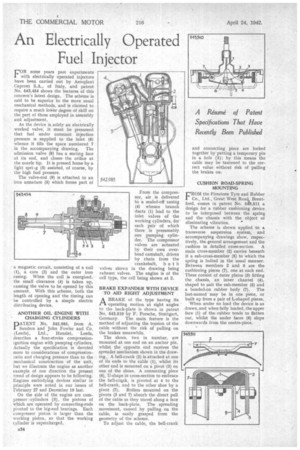
FOR some years past experiments with electrically operated injectors have been carried out by Aeroplani Caproni S.A., of Italy, and patent No. 643,454 shows the features of this concern's latest design. The scheme is said to be superior to the more usual mechanical methods, and is claimed to require a much lower degree of skill on the part of those employed in assembly and adjustment
As the device is solely an electrically worked valve, it must be presumed that fuel under constant injection pressure is supplied to the inlet (6) whence it fills the space numbered 7 in the accompanying drawing. The admission valve (8) has a seating face at its end, and closes the orifice at the nozzle tip. It is pressed home by a light spri.ig (3) assisted, of course, by the high fuel pressure.
The valve-rod (9) is attached to an iron armature (5) which forms part of a magnetic circuit, consisting of a coil (I), a core (2) and the outer iron casing.When the coil is energized, the small clearance (4) is taken up, causing the valve to be opened by this amount. With this scheme, both the length of opening and the timing can be controlled by a simple electric distributing device.
ANOTHER OIL -ENGINE WITH CHARGING CYLINDERS
PATENT No. 542,985, from A. Sanders and John Fowler and Co. (Leeds), Ltd., Hunslet, Leeds, describes a four-stroke compressionignition engine with pumping cylinders. Actually the specification is devoted more to considerations of compressionratio and charging pressure than to the mechanical construction of the unit, hut we illustrate the engine as another example of one direction the present trend of design appears to be following. Engines embodying devices similar in principle were noted in our issues of February 27 and December 19 last.
On the side of the engine are corn.cressor cylinders (3), the pistons of which are operated by connecting-rods pivoted to the big-end bearings. Each compressor piston is larger than the working piston, so that the working cylinder is supercharged.
From the compressor, air is delivered to a sealed-off casing (4) whence branch ducts (1) lead to the inlet valves of the working cylinders, for each pair of which there is presumably one pumping cylinder. The compressor valves are actuated by their own overhead camshaft, driven by chain from the crankshaft, both valves shown in the drawing being exhaust valves. The engine is of the cell type, the cell being shown at 2.
BRAKE EXPANDER WITH DEVICE TO AID RIGHT ADJUSTMENT
ABRAKE of the type having its -operating motion at right angles to the back-plate is shown in patent No. 543,510 by F. Porsche, Stuttgart, Germany. The main feature is the method of adjusting the tension of the cable without the risk of pulling on the brakes meanwhile.
The shoes, two in number, are mounted at one end on an anchor pin, whilst the opposite end receives the spreader mechanism shown in the drawing., A bell-crank (2) is attached at one of its ends to the cable (1), whilst its other end is mounted on a pivot (3) on one of the shoes. A connecting piece (6), U-shape in cross-section to embrace the bell-crank, is pivoted at 4 to the bell-crank, and to the other shoe by a pivot (7). Rollers mounted on the pivots (3 and 7) absorb the direct pull of the cable as they travel along a face on the back-plate. The spreading moveinent, caused by pulling on the cable, is easily grasped from the geometry of the scheme.
To adjust the cable, the bell-crank and connecting piece are locked together by putting a temporary pin in a hole (5); by this means the cable may be tautened to the correct value without risk of pulling the brakes on.
CUSHION ROAD-SPRING MOUNTING
FROM the Firestone Tyre and Rubber Co., Ltd., Great West Road, Brentford, comes in patent No. 54°3,511 a design for a rubber cushioning device to be interposed between the spring and the chassis with the object' of eliminating vibration.
The scheme is shown applied to a transverse suspension system, and accompanying drawings show, respectively, the general arrangement and the cushion in detailed cross-section. A main cross-member (2) carries beneath it a sub-cross-member (5) to which the spring is bolted in the usual manner. Between members 2 and 5 are the cushioning pieces (7), one at each end. These consist of Outer plates (3) fitting the chassis, an inner channel (4), shaped to suit the sub-member (5) and a bonded-on rubber body (7). The last-named may be in one piece, or built up from a pair of L-shaped pieces. When under no load the device is as drawn, and when fully loaded, the upper face (1) of the -rubber tends to flatten out, whilst the under faces (6) slope downwards from the centre-piece.