


THE GILFORD-E.C.C. FB
Page 50
Page 51
Page 52
If you've noticed an error in this article please click here to report it so we can fix it.
DNT-DRIVE TROLLEY-BUS
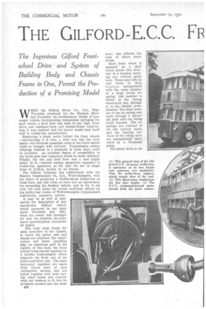
The Ingenious Gilford Frontwheel Drive and System of Building Body and Chassis Frame in One, Permit the Production of a Promising Model Low Loading Height an Outstanding Feature of the New 50-seater, which has a Lowersaloon Floor Less than 14 ins, from the Ground Level
WHEN the Gilford Motor Co., Ltd., High Wycombe, produced for the Olympia Show last November its revolutionary design of passenger vehicle, incorporating independent springing for each wheel, a level floor less than 14 ins, high, front drive, and combined body and chassis-frame construction, it was realized that the layout would lend itself well to trolley-bus manufacture.
Employing a single motor behind the front wheels —encroaching, it is true, a little way into the body space—the foremost passenger seats in the lower saloon could be brought well forward. Transmission noises, although reduced to a minimum in these days, could be localized. An excellent degree of accessibility to the brush gear and contactors would be easily obtained. Finally, the low and level floor and a roof height under 13 ft.—without sunken gangways—appealed to trolley-bus operators, as did also the use of single tyres of 11.25-in. section on all wheels.'
The Gilford Company has collaborated with the Electric Construction Co., Ltd., Wolverhampton, with the object of producing a double-saloon trolley-bus on these lines, and this week we have had an opportunity for examining the finished vehicle, and to try it out with full load under the varied conditions offered by the trolley-bus routes of Wolverhampton Corporation's well-known, extensive system.
It may be as well to summarize the description of this unorthodox Gilford vehicle which appeared in our issue dated November 3rd, 1931, When the power unit arranged for was the Junkers six-cylindered opposed-piston two-stroke oil engine.
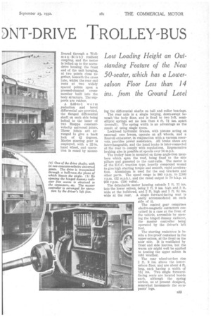
The body shell forms the main structure of the chassis, to which the power unit and wheels are attached. The wheelarches and lower panelling play an important part in the rigidity of this shell, the front arches being braced together by a tubular cross-member which supports the front end of the power-and-drive unit. The main structural members are made from drawn steel of open rectangular section, and are bolted together with bolts having coned heads and countersunk nut washers to fit into depressions pressed into the mem D32 bers ; this relieves the bolts of direct shear stress,
Each front wheel is mounted on a shell which pivots (for steering) in a bracket carrying two vertical guide bars. These may ride up and down in deep bushes incorporated with the outer member of a large Gruss air spring ; this member is bolted to the strong wheel-arch and, through it, to the tubular crossmember. The inner member of the air spring contacts through a universal joint with the riding wheel bracket. The air springs are relieved of all but vertical loads, and the bearing surfaces of the riding units are automatically lubricated by a Tecalemit pump.
The motor drive is de livered through a Wellman-Bibby resilient coupling, and the motor is bolted up to the wormdrive housing, the front end of the unit hanging, at two points close together, beneath the cross tube, whilst the rear end rests at two widely spaced points upon a pressed-channel crossmember built into the body structure. The supports are rubber.
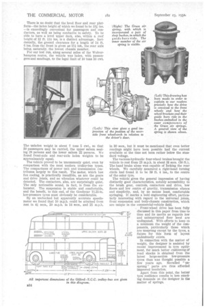
A 9.33-to-1 worm yeduction and bevel differential are provided, the flanged differential shaft on each side being bolted to the inner of two Rzeppa constantvelocity universal joints. These joints are arranged to give a back lock of 42 degrees. Manes steering gear is employed, with a 22-in. hand wheel, and operation is eased by mount ing the differential shafts on ball and roller bearings.
The rear axle is a single forging, down-swept beneath the body floor, and is fixed to two 5-ft. semi elliptic springs set no less than 4 ft. 74 ins. apart (overall). The spring width is an advantage as the result of using single tyres.
Lockheed hydraulic brakes, with pistons acting on external cam levers, operate on all wheels, and a Reavell exhauster, in conjunction with a vacuum reservoir, provides power assistance. All brake shoes are interchangeable, and the hand brake is inter-connected at the rear to comply with regulations. Regenerative braking also is possible at speeds over 14 m.p.h.
The trolley base is mounted on three angle-iron members which span the roof, being fixed to the side pillars and gusseted to the cant-rails. The motor is of the E.C.C. traction type, heavily compound wound to give high starting torque and smooth, rapid acceleration. Aluminium is used for the end brackets and other parts. The speed range is 900 r.p.m. to 2,500 r.p.m. (32 m.p.h.), and the rated output is 70 b.h.p. at 900 r.p.m. (500 volts).
The detachable motor housing extends 1 ft. 11 ins. into the lower saloon, being 2 ft. 9 ins. high and 3 ft. wide at the bulkhead, and 2 ft. high and 1 ft. 81 ins. wide at the rear. A single forward-facing seat is easily accommodated on each side of it.
The control gear comprises electro-magnetic contactors contained in a case at the front of the vehicle, accessible by opening the hinged dummy radiator, the master controller being operated by the driver's left foot, The starting resistance is inside a tire-proof container in the upper saloon, at the front on the near side. It is ventilated by front and side louvres, but the warm air might well be applied to heating the upper saloon in cold weather.
The rear wheel-arches rise 2 ft. 9 ins, above the lowersaloon floor, and are about 4 ft. long, each having a width of 131 ins. Two single forwardfacing seats are located beside each, although the spring arches, as at present designed, somewhat incommode the occupants' legs.
There is no doubt that the level floor and rear platform—the laden height of which we found to be 134 ins. —is exceedingly., convenient for passengers and conductors, as well as being conducive to safety. To be able to have a level upper deck, also, within a roof height of 12 ft. 11* ins, is a distinct advantage. Incidentally, the ground clearance for a length of 14 ft. 0 ins, from the front is given as llj ins., the rear axle being, naturally, the lowest chassis member.
For our test run, along several miles of the Wolverhampton routes, the vehicle was laden, with passengers and sandbags, to the legal limit of 10 tons 10 cwt.
The unladen weight is about 7 tons 5 cwt., so that 50 passengers may be carried, the upper saloon seating 28 persons and the lower saloon 22 persons. We found front-axle and rear-axle laden weights to be approximately equal.
The vehicle proved to be uncommonly quiet, even by comparison with the most modern trolley-bus types. The compactness of power unit and transmission contributes largely to this result. The motor, which has fan cooling, is practically inaudible, as are the gears and drive joints, and no vibration whatever could be detected. The contactors, also, are surprisingly quiet. The only noticeable sound, in fact, is from the exhauster. The suspension is stable and comfortable, and the benefit, to this end, of the Goodyear 11.25-in. low-pressure tyres must obviously be considerable.
By an unchecked but apparently accurate speedometer we found that 10 m.p.h. could be attained from rest in 4i secs., 20 m.p.h. in 14 secs., and 25 m.p.h. in 30 secs., but it must be mentioned that even better readings might have been possible had the current available at the time not been rather below the standard voltage.
The vacuum-hydraulic four-wheel brakes brought the vehicle to rest from 23 m.p.h. in about 3-Esecs. (50 ft.). The hand brake alone was capable of rocking the rear wheels. We carefully measured a right-hand turning circle had found it to be 59 ft. 4 ins., to the centre of the outer tyre.
The vehicle gives the general impression of having distinctly good characteristics, notably accessibility to the brush gear, controls, contactors and drive, low floors and low centre of gravity, transmission silence and simplicity, and, by no means least, comfortable springing. It marks a bold engineering effort, particularly interesting with regard to the universal joints, front suspension and body-chassis construction, which are unique in the commercial-vehicle field.
Front-wheel drive has been fully discussed in this paper from time to time and its merits as regards low and unintet:rupted floor level are undisputed. With efforts to keep to a minimum the weight of the components, particularly those which are unsprung except by the tyres, a future for this form of layout undoubtedly exists.
In connection with the matter of weight, the designer is assisted by recent improvement in tyre equipment, for much better cushioning of road shocks is obtained from the latest large-section low-pressure tyres than was thought possible a few years ago. So-called " unsprung " parts are thus afforded improved insulation.
Apart from this point, the better tyre resilience results in less exacting demands on the designer in the matter of springs.