


HINTS ON MAINTENANCE.
Page 30
If you've noticed an error in this article please click here to report it so we can fix it.
How to Get the Best Out of a Vehicle, to Secure Reliability and to Avoid Trouble.
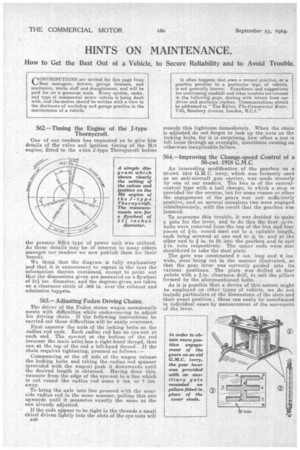
562.—Timing the Engine of the J-type Thornycroft.
One of our readers has requested us to give him details of the valve and ignition timing of the M/4 engine, fitted to the 4-ton J-type Thornycroft before the present BB/4 type of power unit was utilized. As these details may be of interest to many others amongst our readers we now publish them for their benefit.
We think that the diagram is fully explanatory and that it is unnecessary to repeat in the text the information therein contained, except to point out that the dimensions given are measured on a flywheel of 213/4 ins, diameter, and the degrees given are taken on a clearance circle of .008 in, over the exhaust and admission tappets.
563.—Adjusting Foden Driving Chains.
The driver of the Foden steam wagon occasionally meets with difficulties while endeavouring to adjust his driving chain. If the following instructions be carried out these difficulties will he easily overcome.
First unscrew the nuts of the locking bolts on the radius rod ends. Each radius rod has an eye-nut at each end. The eye-nut at the bottom of the rod (nearest the main axle) has a right-hand thread, that one at the top of the rod a left-hand thread. If the chain requires tightening, proceed as follows :—
Commencing at the off side of the wagon release the locking bolts and taking the radius rod spanner (provided with the wagon) push it downwards until the desired length is obtained. Having done this, measure from the edge of the eye-nut to a line which is cut round the radius rod some 6 ins. or 7 ins. away.
To bring the axle into line proceed with the nearside radius rod in the same manner, pulling this one upwards until it measures exactly the same as the one already adjusted.
If the rods appear to be tight in the threads a small chisel driven lightly into the slots of the eye-nuts will 1346 remedy this tightness immediately. When the chain is adjusted do not forget to lock up the nuts on the locking bolts, for it is surprising how often a nut is left loose through an oversight, sometimes causing an otherwise inexplicable failure.
564.—Improving the Change-speed Control of a 50-cwt. 1918 G.M.C.
An interesting modification of the gearbox on a 60-cwt. 1918 G.M.C. lorry, which was formerly used as an anti-aircraft gun carrier, was made recently by one of our readers. The box is of the centralcontrol type with a ball change, in which a stop is provided for the reverse, but for some reason or other the engagement of the gears was not sufficiently positive,•and on several occasions two were engaged simultaneously, with the result that the gearbox was jammed.
To overcome this trouble, it was decided to make a gate for the lever, and to do this the four 17w-in. bolts were removed from the top of the box and four pieces of g-in. round steel cut to a suitable length, each being screwed at one end to is in. and at the other end to # in. to fit into the gearbox and to suit nuts respectively. The upper ends were also shouldered to take the steel plate.
The gate was constructed 8 ins, long and 6 ins. wide, slots being cut in the manner illustrated, so that the gear lever was correctly guided into its various positions. The plate was drilled at four points with a f-in. clearance drill, to suit the pillars
formed by the aforementioned bolts. .
As it is possible that a device of this nature might be employed on other types of vehicle, we do not include particulars of the dimensions of the slots and their exact position' these can easily be ascertained in individual cases by measurement of the movement of the lever.