


SAFETY IN WHEEL CONSTRUCTION.
Page 27
Page 28
Page 29
If you've noticed an error in this article please click here to report it so we can fix it.
The Stresses Encountered. Wheel Collapse a Serious Danger. The Results of Recent Tests and Deductions Therefrom.
COMPAEATIVRLY little space in the technical Press has been devoted to the subject of wheels for motor vehicles, and yet there appears to be ample scope for many interesting observations, for one has only to examine a few vehicles to realize that wheel designs are almost infinite in their variety, whilst the materials employed include wood, cast steel, pressed steel and various applications of steel beams of different sections, whilst, more recently, several examples of aluminium wheel have been developed ; but in this country the wood wheel has almost fallen into disuse, with the exception of those employed an light vehicles, chiefly of foreign origin.
The first matter to be considered is the stresses to which-a wheel is liable to be subjected. It might be thought that the greatest of these would be the weight which it has to carry, but, actually, this is almost a minor consideration, but it has a bearing upon the subject, as it adds to whatever other stresses are encountered.
The Chief Stresses to which a Wheel is Subjected.
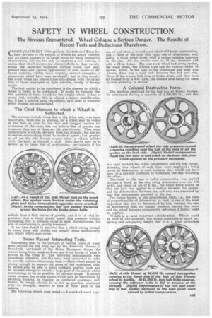
The stresses include those due to the drive and, even more . important, those due to braking, for a wheel may be locked at the hub or close to the hub and dragged against the resistance of the road, but we believe that of greater consequence than any of these are the side thrusts. They occur immediately a vehicle deviates from the straight, but are not excessive unless sharp turns be made at speed; but greatest of all are the side thrusts caused when a vehicle collides 'with the kerb, as through a skid. Such shocks may be so Severe as to cause risk of overturning, particularly if the
vehicle have a high centre of gravity, and it is of vital importance that awheel should stand this pressure without collapsing, for, if collapse occur in suchcircumstances, the risk of overturning is greatly increased. •
It has been found in practice that a wheel strong enough to resist these side shocks can usually resist satisfactorily any others which may occur.
Some Recent Interesting Tests.
Interesting tests of the strength of various types of wheel were carried out not long ago by the American Bureau of Standards on•behalf of the Motor Transport Corps, the wheels being those used, on 3-ton and 5-tori lorries of what is known as the • Class B. The following requirements were considered essential, and the tests were conducted in order to provide opinion concerning them :—Each wheel should be strong enough to support its share of the maximum load. It should also be able to resist suddenly applied loads and be resilient enough to absorb a large part of the shock whilst maintaining, so far as possible, its circular shape. It should resist stresses due to side thrust which may be introduced by skidding; turning, or running on cambered roadways, and finally, its weight should be as /ow as possible, consistent with its strength, relative to that of other parts of the ;vehicle.
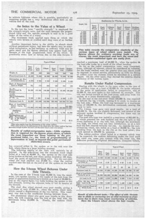
The fallowing wheels were tested standard wood type,
one of cast-steel, a second steel wheel of I-beam construction, and a third of the steel disc type, one of aluminium, and, lastly, a wood wheel fitted with a rubber cushion insertion in the rim. All the wheels were of 34 ins, diameter and with a I2-in. tread. The cast-steel wheel had seven spokes, the wood wheel, the I-beam type and the cushion wheel 14 spokes, whilst, in the case of the aluminium and steel disc wheel; there was a solid web between the huh and rim. Nona of the wheels had tyre or brake drum, and they were all bushed to fit a 4-in, axle, the contact area being the same as that occurring in service.
A Colossal Destructive Force.
Themachine employed for the test was an Emery hydraulic instrument having a capacity of 2,300,000 lb., and this was used for both the radial compression and the side thrust. Actually, two wheels of each type were employed; being tested to destruction in each instance they would not have been in a suitable condition to withstand one test following the other. The load, in the case of radial compression, was applied through a block at the rim, being distributed over the full width and along an are of 6 ins., the wheel being placed so that the load was applied to a section between the spokes, and the deformation between rim and axle was measured by four dial micrometers attached to the rim.
The factor known as the proportional limit, i.e., the limit of proportionality of deformation to load, is one of the most important that can be determined by test, because the rate of deformation does not remain constant beyond that point and the wheel, becomes permanently deformed if higher loads be applied.
Weight is a most important consideration. Wheels could be built of any strength, but would constitute so much unsprung and non-paying weight that it is a great advantage to achieve lightness where this is possible, particularly as unsprung weight has a very deleterious effect both on the vehicle and on the road.
An Index to the Value of a Wheel.
In the test the term "specific strength" is employed for the strength-weight ratio, and the ratio between the proportional limit' and the specific strength -is said to be a good index of the value of a wheel.
The maximum loads applied were those at which the wheels were broken or crushed until they were of no further use.
Another important factor is the ability to absorb shock without permanent injury, but here the results may be somewhat inconclusive, as the resiliency at ordinary loads may be quite small and the figures obtained raay appear high only because of the high proportional limit of the wheel. In practically every case of failure due to the side thrusts it has occurred either in the spokes or in the web near the hub, where there is a large bending moment. The following results of the tests will certainly be of interest. In the side-thrust test the standard wood wheel failed at a load of 40,000 lb., the spokes on the road side being broken at the hub, and three spokes located at, 180 degs. from the point of application being split. For the cast-steel wheel the load reached was 57,000 lb., when the casting cracked near the hub at the end of all the spokes on the load side.
How the I-beam Wheel Behaves Under Side Thrusts.
In the case of the I-beam type 45,500 lb. was the maximum, two spokes running to the inside of the, hub from the point of application beginning to buckle at a load of 38,0001b., and at the higher figure two bolts holding the spokes to the huh sheared, causing the adjacent bolts to fail in tension at the threads.
The steel disc wheel showed very poor results, giving a maximum of only 27,000 lb., when the entire wheel bent, which caused a displacement of the two halves. This weakness was due to the ,nsufficient bracing between them.
The aluminium wheel also gave poor results in this direction, the web cracking near the hub at the load side, the maximum being 23,0000 lb. Finally, the cushion wheel reached a maximum load of 64,000 lb,, when the spokes eh the load side liroke as a result of the wheel bending.
So far as the radial compression tests were concerned, these, although of interest, cannot be considered so valuable, for the loads reached were far greater than any which could be imposed in actual service, particularly as with tne fitting of rubber tyres the stresses would be absorbed to a certain degree. On the other hand, they showed the relative elastic resiliency of the various types.
Results Under Radial Compression.
Dealing with the wheels in the same order, in the case of the artillery type, at a load of 85,000 lb. the spoke adjacent to the point of application failed in compression, and at 95,000 lb. the next spoke to this followed its example. The rim was forced inward at the load point, and away from the spokes at a paint diametrically opposite. In the case of the cast-steel wheel 155,000 lb. was required to deform the ■-im iywards causing it to crack in tension at the hub side. When the foad was increased to a maximum value of 185,000 lb. the deformation continued, causing the crack to open.
The I-beam type gave very good results. At a load of 148,000 lb. the rim was slightly deformed, 'and several of the adjacent spokes buckled in compression, but there was no actual breakage.
The-steel disc type was tested to a maximum of 203,000 lb., at which pressure the web buckled and the rim split at the rivets fastening it to the web, but, although the maximum was high, the wheel was not very satisfactory, as at a low load the hub sheared towards the rim. As regards the castaluminium wheel, this failed at a load of 80,000 lb., the web cracking from the hub to the rim at the load point ; this crack opened at 190,000 lb. pressure.
The rubber-cushion wheel failed in a manner which was to be expected, the cushion deforming under the load until the outer rim came into contact with the inner one, the deflection producing elliptical deformation. Complete failure,
lee to cracking of two of the spokes, occurred at a maximum if 210,000 lb.
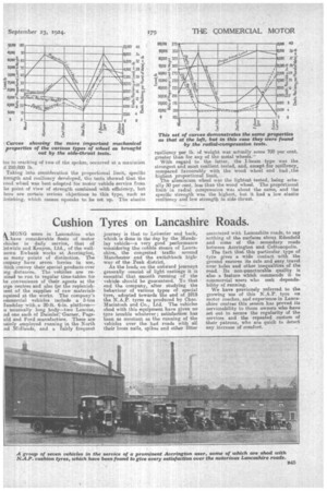
Taking into consideration the proportional limit, specific trength and resiliency developed, the tests showed that the vood wheel was best adapted for motor vehicle service from he point of view of strength combined with efficiency, but here are certain serious objections to this type, such as lirinking, which causes squeaks to be set up. The elastic resiliency per lb. of weight wa,s actually some 700 per cent. greater than for any of the metal wheels.
With regard to the latter. the I-beam type was the strongest and most resilient tested, and, except for resiliency, compared favourably with the wood wheel and had the highest proportional limit.
The aluminium wheel was the lightest tested, being actually 30 per cent, less than the wood wheel. The proportional limit in radial compression was about the same, and the specific strength was the highest., but it had a low elastic resiliency and low strength in side thrust.