


M.I.R.A. Transmission H YDRAULIC transmissions of the pump and fluid-motor type
Page 66
If you've noticed an error in this article please click here to report it so we can fix it.
give an infinitely variable ratio, hut their efficiency is usually so low that they can he used only in specialized applications. Atransmission system shown in patent No. 819,999 utilizes hydraulic mechanism, but only to bridge the gap between two mechanical ratios, so that the
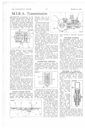
hydraulic efficiency is not of paramount importance. (The Motor Industry Research Association, Lindley, near Nuneaton, Warwickshire.) The drawing shows a two-speed gear that provides also any ratio between the two fixed ones. The mechanical part is epicyclic; if the sun-wheel (1) is locked one ratio is engaged, whilst the other ratio is obtained by locking the annulus (2). If either gear is allowed to rotate slowly, an intermediate ratio is obtained.
Controlled rotation is provided by a pair of side-by-side hydraulic units (3). The rotor of one is connected to the sun-wheel and the other to the annulus. The units are of the eccentric-vane type. and the output of one is led to the intake of the other, so that one is driven by the other at a speed dependent upon their eccentricities.
The eccentricity can be varied by an external control (4) which simultaneously shifts both casings diametrically, moving one unit to greater output whilst the output of the other is reduced. The hydraulic system has been more fully described in an earlier patent numbered 766,659, to which the present patent is an addition, covering the control system.
PALLET LOADING DEVICE
PATENT No. 820,055 describes apparatus to facilitate the loading of vehicles with palleted goods. (W. Herbert, A. Line and Carrimore Six
Wheelers. Ltd., all of Carrimore Works, Great North R o a d, London, N.12.) The drawing shows the rear end of a semi-trailer according to the invention. The novel feature is the provision of mechanism for moving a pallet from the tailboard to the front of the vehicle.
The mechanism comprises an endless chain (1) which runs in a central channel in the floor of the body. The chain passes over a rear sprocket (2), a front sprocket (not shown) and then around a sprocket (3) on a gearbox. The chain returns to the rear via sprocket (4) which is fitted with a tensioning device (5).
In operation, a fork-lift truck places the pallet on to a trolley resting on the tailboard. The trolley has a projection which engages with the chain, A handle on the spindle (6) is then turned manually to haul the trolley to the front.
The tailboard normally lies in the upright position (7) but is lowered for loading. A pair of extending members (8) is provided to support the tailboard when horizontal.
INTERRUPTED INJECTION
AN injector described in patent No. 819,607 is made to give, instead of smooth discharge, a series of spurts. This is claimed to promote smooth running. (Adolph Saurer, Ltd., Arbon, Switzerland.)
The drawing is a section of the proposed injector and shows the parts used to create the interrupted flow. Fuel arriving at the top will flow down to the nozzle but must pass a disc-valve (1) having a very slight clearance around it. The disc-valve is closed by its own separate spring (2).
As the pressure builds up in the lower chamber it forces open the nozzle valve (3) to commence injection. With an increased flow of fuel, it cannot all pass through the clearance around the disc valve, so that it is opened by the pressure rise. This action is said to set up an oscillation of the nozzle valve and so provide a " stuttering " charge of fuel.
TRANSFER GEARBOX
ATRANSFER gearbox for fourwheel-drive vehicles in which the front wheels only are normally driven is described in patent No. 814,210. It is designed for compactness and ease of manufacture on a production basis. (Auto Union G.m.b.H., 3 Schrannenstrasse, Ingolstadt, Germany.)
The clutch shaft (I) drives a small twospeed gear, shown generally at 2. This is illustrated as a reduction gear, but could alternatively be an overdrive. A dog clutch (3) renders the gear operative, or alternatively, gives a straight-through drive to the main gearbox.
The gearbox has two output shafts, one for front-wheel drive and one for the rear wheels. The former carries a bevel pinion (4) which drives the differential gear (5), whilst the latter emerges at the opening 6 for the attachment of a cardan shaft. Rear-wheel-drive can be disconnected by a dog clutch (7).
PROGRESS IN SURFACEDISCHARGE SPARKING PLUGS PATENT No. 810.680 shows a sparking plug operating on the surfacedischarge principle. (K.L.G. Sparking Plugs, Ltd., Putney Vale, London, S.W.15.)
The central electrode is surrounded by an insulator, the lower face (1) of which is coated with a semi-conductive material, and the spark occurs over this surface.
This particular plug is provided with an internal capacitor consisting of an insulating sleeve (2). coated on both sides with metal. The inside is in contact with the centre terminal (3) and the outside with earth. When the current arrives, it charges this capacitor until a small air-gap between them is broken down. This ensures that a certain minimum voltage is built up across the discharge area before any current can traverse it.