


WAYS AND MEANS.
Page 69
If you've noticed an error in this article please click here to report it so we can fix it.
Useful Contributions from our Driver and Mechanic Readers.
Cutting Screws in a Plain Lathe.
T 013S of turning and even screw!) cuttiw, have often to be done in places that are poorly equipped so far as lathes are concerned, and any advice that will enable such work to be carried out with a small equipment may be of great value in a time of need, and a mental note should impress the follow
' ing tips on the minds of all who are likely to have to do such jobs.
" J.B.J.," of Croydon, sends us particulars of two ways by means of which screw threads, both inside and outside, can be cut when no screw-cutting lathe is available.
There are two ways by which screws can be cut with fair accuracy on any ordinary plain lathe. Taking for a start the cutting of a thread on a bolt or shaft, if a chaser is to be found that will fit the number of threads per inch required, there is no trouble. Some people will take a chaser and try to strike a thread with it ; this can be done by an. experienced brass finisher, but it is very difficult and can hardly be done in iron or steel, as the chaser is almost certain to slip before any proper impression can be made.
With a thread inside a hole our contributor is certain that there is hardly a turner in the laud who could strike such a thread in steel and rely on it being passably accurate.
To cut an outside thread, take a slide rest tool ground to a yes, and after having turned the part to a diameter slightly larger than required when finished, run the latheat a rather slow speed and wind the tool along as the work revolves, trying as nearly as possible to produce a thread of the required pitch. You will probably find that the mark made by the tool is something like that shown in the illustration ; too fine at first and getting coarser as it goes on. or it may be too coarse at first and become finer farther on. Now if the chaser be matched up to this you are almost certain to find some part of your thread that fits the chaser for, perhaps, three turns. All the part that is not correct should then be turned down to the finished diameter, which will remove the shallow groove made by the vee tool and which has been allowed for in the increased diameter of the part in question.
The chaser can then be used, following the tool groove until the chaser gradually begins to make a groove all along the job. Screws have been cut in this manner that showed no signs of being "drunk," as most threads do that have been cut in a plain lathe.
Another way, and one that is best for inside work, is to make four marks on the work or chuck, that is providing the screw of the top slide has four threads per inch, and fix to the screw of the slide any kind of disc that may be handy ; a wooden one will do.
The disc is marked off in rough divisions corresponding with the number of threads per inch required. Some kind of pointer must be fixed up to both the divisions on the chuck and that on the disc on the screw. An ordinary screw-cutting tool is held in the rest, the lathe put in gear, pulled round slowly by the belt and the tool wound along, taking care that as each division on the chuck passes from mark to mark, those on the screw do the same.
It is true that local errors may occur, but at every quarter turn of the lathe the travel of the tool is brought to the correct place. The effect is as if the screw of the slide rest were geared to the mandrel.
The rule for finding the ratio is to divide the chuck into as many divisions as there are threads per inch in the slide screw, and to divide the disc into the number of threads per inch required. After a few runs along like this, a chaser can finish off, and if carefully done quite a satisfactory thread will result.
Overload Safety Valves for Hydraulic Tipping Gears.
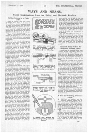
IN your issue of December 15th, 1925, writes H.W,S., of Bolton, there was an article dealing with a safety or overload valve for hydraulic tipping gears to prevent the chassis being strained in the event of the operator forgetting to release the holding-down pins of the body.
" Appended is a sketch of an overload valve for the same purpose, which has been standardized and used for some considerable time on the Edwards patent end and three-way tipping gears.
The valve body is of gunmetal and is attached to the oil pump at the side of the oil reservoir, the oil being pumped from the reservoir through the passage marked on the sketch to the hydraulic ram.
Should the holding-down pins be left in, the pressure of the oil is increased until it reaches that set on the overload spring, when the ball and spring are forced back and the oil simply by-passes through the pipe provided, to be returned to the pilini) box, thus preventing any damage being done to the chassis and at the same time the oil is prevented from running to waste.
One thing of especial note on the valve is that by judicious use of the adjusting nuts, the working pressure of the tipping gear can be varied at will to suit any particular load.
A Tool for Grinding Overhead Valves.
A SIMPLE yet efficient tool fey grinding overhead valves can be made, says " C.C.," of Yetlington, from I-in, round steel, 5 ins, long, turned down in the lathe for 2 ins, at each end
to the thickness of in. A fin, hole should be drilled through the body, and a hole drilled in the side for a i-in. setscrew.
The valve seat is smeared with grinding paste and placed in position, the tool is slipped over the end of the valve stem and the setscrew tightened, the device is then ready for use.
It is useful to note that paraffin mixed with the paste makes it c.ut quicker.