


MODIFICATIONS IN A LOW-LEVEL CHASSIS:
Page 52
Page 53
If you've noticed an error in this article please click here to report it so we can fix it.
The Latest Star Passenger Model Now Equipped with a Six-cylindered Engine for High-speed Work.
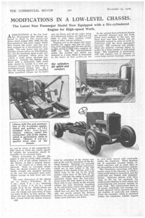
A DESCRIPTION of the low load11 line 20-passenger Star chassis appeared in detail in The Commercial Motor dated August 10th, 1928, but the four-cylindered side-valve engine which then formed the power unit has now been replaced by a six-cylindered o.h.v. model. The new power unit not only provides greater power for hill-climbing, etc., but the maximum speed is also con-. sideranly increased, which gives the vehicle a much better all-round performance. Actually the cliassis, when fitted with a moderately light coach body, should be capable of a road performance almost equal to that usual in medium-powered touring 'cars. As a bus the outlying districts of somewhat thinly populated villages can be linked
up, and by virtue of the comparatively high speed of which the vehicle should be capable the proposition should be workable on an economic basis.
Before proceeding to describe the engine it may be worth while recapitulating a few of the salient features of the chassis, so that a general impression of the vehicle as a whole can be obtained. Built on extremely simple lines, the chassis consists of two practically straight side members upswept at the rear and suspended upon semielliptic springs at both front and rear axles.
The main dimensions of the chassis are as follow :--Wheelbase, 12 ft. 4 ins.; track, 5 ft. 1 in. ; maximum width of frame, 3 ft. Oi in.; overall length, 18 ft. 4/,ins. Single wheels are fitted at the front and twins at the rear, the wheels and tyres being of Dunlop make of 32-in. by 8-in, section. The frame has four channel-steel cross-members, around which the various compon
c30
eats are fitted, and all the units, being of a substantial nature, are rigid and not liable to whip when crossing rough roads or other uneven surfaces.
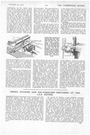
Turning now to the engine and transmission, the power unit has six cylinders of 75 ramliomand120 ram. stroke, injhe, givinga.total' cubic capacity of 3,180 c.c. Like Wm four-cylindered model, the gearbox and clutch are mounted as a unit, which is suspended in the frame at four points—at the front by extensions of the timing ease and at the rear by extensions of the flywheel housing. Brackets are mounted on the extreme end of these extensions, which are in turn bolted to the side members of the chassis frame, and a lip which rests on the top of the frame member takes most of the load off the bolts. Although the engine Is naturally somewhat longer than the four-cylindered model the body space is not interfered with to any extent, as the steering column has been shortened (resulting in the wheel being nearer the dash) and the pedals have been moved forward, which does not alter the leg-room available, but merely reduces the distance between the pedals and the dash ; thus waste space has been cut down.
In the original four-cylindered chassis the centrally disposed gear and brake levers Were inclined to the rear, but these have now been altered and are practically vertical in order to avoid interference with the front passenger's leg-room. The crankcase and cylinder block are seParate castings bolted together by a large number of well-placed studs. The crankshaft is particularly stiff and massive and is mounted in ;-even large journal bearings, which are
in turn slit*" braced with cross-webs within the crankcase. These bearings are of somewhat unusual design, to which reference will be made later in the description of the lubrication system.
The Duralumin connecting rods have bronze cages in the big-ends, in which a white-metal lining is introduced, and the small-ends are bushed with phosphorbronze. Cast-iron pistons with three rings at the top are employed, the gudgeon-pins floating in bath piston and connecting-rod and secured endwise by keep rings. The cylinder-head block is, of course, detachable and contains vertically disposed valves operated through the medium of push-rods and rockers. From the camshaft, which is contained within the crankcase, tubular tappets
communicate, via the tubular pushrods, with the rockers for the overhead valves; an interesting feature concerning this arrangement being the fact that loose balls are used at both top and bottom ends. Several advantages are claimed for this layout, one being the fact that as the balls are continually moving (being rotated in all directions) there is a much greater surface available over which wear can be distributed ; and, another, the fact that it is difficult to get a hardened steel ball formed in one piece with an adjuster without risk of breakage at the end in which the screwdriver slot is formed. The ends of the tappets do not rest upon the cams, but slippers are interposed, which are mounted upon brackets bolted to the outside of the crankcase. Each bracket
contains two slippers, and by virtue of their position they can be withdrawn easily for examination or replacement. Both the push-rods and the rocker mechanism are enclosed, the latter by means of an aluminium cover, which is attached to the upper face of the cylinder head.
Turning now to the lubrication system, a pinion-type pump submerged in the sump is driven by skew gears from the rear end of the camshaft and forces oil to a filter pocket formed in the rear near-side engine-bearer arm. From this pocket a channel running along the near side of the crankcase communicates by internally drilled passages in the main bearing webs to the main bearing journals themselves, also to the camshaft bearings. In each of the main bearings an annular groove is formed, a hole. in the cap allowing excess oil to drain into
the sump again. The sump itself has a false bottom, in whichtroughs are formed into which the connecting-rods dip. Now these troughs are fed in two ways—one by the drainage from the main bearings and the other by a pipe leading over the distribution gears, with a suitable drain lodding to the troughs. When correctly set 5 lb. pressure in the system is all that is required, but a large quantity of oil is constantly in circulation.
Part of the main oil supply is led to the overhead-valve gear through an external pipe which feeds into the rear of the cylinder head and through the rear standard to the hollow rocker shaft. Each of the rockers is drilled with holes communicating with further holes in the shaft itself, a channel along the top of the rocker leading the oil to both the ball end of the push-rod and to the end of the rocker which bears upon the valve stem. Actually there are two rocker shafts, connected by a telescopic joint, in order to allow for expansion or contraction when the engine is running at varying temperatures. On the two abutting rocker-shaft standards cone seatings are formed with a spring interposed between two conical washers, which actually form a pressure-release valve, and if an excessive amount of pressure be developed within the oiling system these washers are forced off their seatings, thus allowing oil to escape.
Both inlet and exhaust manifolds are formed as a unit, the junction of the inlet pipe constituting an excellent hotspot. The carburetter—a Solex—draws its air supply from a passage which runs longitudinally along the crankcase, and
is thus heated before it reaches the engine. In addition a copper pipe connects between the overhead-valve cover and,, the carburetter intake to enable the oily mist within the casing to be taken through into the engine again. This arrangement not only tends to keep the engine clean, but also minimizes oil waste and provides lubrication for the inlet-valve stems and the top portions of the piston.
The distribution of the auxiliary drive is obtained by three skew gears, the centre one (on the end of the camshaft) being made of Fabroil in order to ensure silent running.
The water pump is mounted on the top front part of the timing case, and the dynamo and magneto are driven in tandem through the medium of Simms vernier couplings. Provision is made for the magneto to be moved forwards into the place usually occupied by the dynamo in case of failure of the latter instrument. Both the dynamo and battery are of sufficient capacity to supply a five-lamp set on the exterior of the vehicle, the interior lighting necessary for a bus and an electric starter.
Continuing the brief résumé of the chassis details, a plate lutch and four forward-speed gearbox convey the drive. through the medium of a divided open propeller shaft which has a Skefko self. aligning centre hearing carried in a bracket slung from a cross-member. The rear axle is an inverted pot-type steel stamping of Kirkstall make. The price of this very interesting chassis is £590, complete with one spare wheel, but no tyre and it represents excellent value for money.