


MANY TRACTOR INVENTIONS.
Page 28
If you've noticed an error in this article please click here to report it so we can fix it.
A Résumé of Recently Published Patents. •
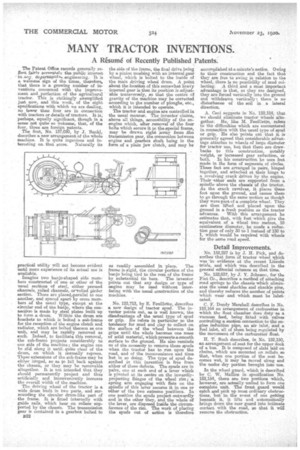
The Patent Office records generally refleet fairly errerrately the-publie interest ' inear-„Y. departuaSurtia engineering. It is a weleume sign of the times, therefore, that there is a growing number of inventions concerned with the improvement and . perfection of the agricultural tractor. This is strikingly exemplified just now, and this week, of the eight specifications with which we are.dealing, no fewer than four are in connection with tractors or details of tractors. It is perhaps, equally significant, though in a same not quite so welcome, that, of the four, three are foreign patents. The first, No. 137,050, by J. Bankl, describes a new arrangement of the whole naachine. It is quite ingenious and intere.sting on that score. Naturally its practical utility will not become evident until more experience of its actual use is available.
Imagine two banjo-shaped side momhers constructed of one or other of the usual sections of steel, either pressed channels; rolled channels, orerolled girder section. These are placedeparallel to one another, and spaced apart by cross members of the usual type, except at the circular end of the banjo, where the connection is made by steel plates built up to farm a drum. Within the drum are larackete to which is bolted a eab-frame for the reception of the engine clutch and radiator, which are bolted thereon as one tmite and may be rapidly removed as such. Indeed, to facilitate this removal, the sub-frame projects considerably to one side of the machine; the engine can he slid along it -until_ quite clear of the drum, on which it normally' reposes. Thescu extensions of the sub-frame may be either hinged, so as DO fall back against the chassis, or they , may be removable altogether. It is not intended that they should permanently project and thus artificially and inconveniently increase the overall width of the machine.
• The driving wheel of the tractor is a wide drum built in two parts, and surrounding the circular drum-like part of the frame. It is fitted internally with guide rails, which bear on rollers supported by the chassis. The transmission gear is contained in a gearbox bolted to
822
the side of the frame, the final drive being by a pinion meshing with an internal gear wheel, which is bolted to the inside of the main driving wheel drum. A point about the location of this somewhat heavy internal gear is that its position is adjustable transversely, so that the centre of gravity of the maehine may be corrected according to the number of ploughs, etc., which it is intended to operate. The tractor and engine are controlled ia the usual manner. The inventor claims, above all things, accessibility of the enengine which, after removal of the four bolts which secure it to thespecial frame, may be drawn right ;away bean the transmission gear, the connection between engine and gesztoir shaft being in the form of a plain jaw clutch, and may be
as readily assembled in place. The frame is-rigid, the circular portion of the Banjo being tied to the rest of the frame by substantial tie bars. The inventor points out that any design: or type of engine may be used without interfering with the usual construction of the machine.
No. 123,713, by E. Feuillette, describes a new design of tractor spud. The inventor points out, as is well known, the disadvantage Of the -usual type of spud or grip. He refers in poetic-War to the tendency for mud and clay to collect on the surface of the wheel between the grips until the whole becomes one mass of solid material, which presents a =moth surface to the ground. He also reminds us of the necessity to remove these spuds when the tractor has to run upon the road, and of the inconvenience and time lost in so doing. The type of spud described in this invention is free from either of these defects. The spuds are in pairs, one at each end of a lever which is pivoted at its centre on the inwardly-projecting flanges of the wheel rim; a spring arm engaging with flats on the spindle of this lever secures it in one or other of the two extreme positions. In one position the spuds project -outwardly and in the other they, and the whole of the lever, are disposed inside the circumference of the rim_ The work of placing the spuds out of action is therefore accomplished at a minute's notice. Owing to then construction and the fact that they are free to swing in relation to the wheel, there is no possibility of mud collecting. A third and a most important advantage is that, as they are designed, they are forced vertically into the ground and withdrawn vertically : there is no d5stamlasinee of the soil in a lateral direction.
A. Coed suggests in No. 152,184, that we should eliminate tractor wheels altogether. He, like M. Feuillette, refers to the difficulties which are encountered in connection with the usual type of spud or grip. He also points oet that it is generally agreed that considerable advantage attaches to wheels of large diameter for tractor use, but that there are drawbacks to this construction, notably weight, or increased gear reduction, or both. In his -construction he uses feet made in the form of segments of circles.. These feet are arranged in pays, hinged together, and attached at their hinge to a revolving crank driven by the engine. Their -ether ends are supported from a spindle above the chassis of the tractor. As the crank revolve; it places these feet upon the ground, and causes them to go through the same motion as though they were part-of a complete wheel. They axe then lifted and placed upon theground in a fresh position as the tractor advances. With this arrangement he estimates that, with feet which give the equivalent of a *heel two metres, 10 centimetres diameter, he needs a reduction year of only 30 to 1 instead of 150 to 1, which would be required with wheels for the same read speed.
Detail Improvements.
No. 152,227 is by J. H. Pick, and describes that form of tractor wheel eyh.ich was in evidence at the recent Lincoln trials, and which was described in the general editorial coln.mna at that time.
No. 152,037, by J. Y. Johnson, for the Fiat Co., describes a method of attaching road springs to the chassis which eliminates the usual shackles and shackle pins, and thereby reduces the umber of points which wear and which must be lubricated.
C. F. Dandy Marshall describes in No. 152,164 an arrangement of carburetter in -which the float chamber does duty as a -vacuum feed, being fitted with valves controlling a ruction connection to the engine induction pipe, an air inlet, and a fuel inlet, all of them being regulated by the movement of the carburetter float.
H. T. Bush describes, in No. 152,150, an arrangement of seat for the upper deck of a bas. It is composed of slats laid on chains, -which are mounted on rolleas so that, when one portion of the seat becomes wet, it may he moved along and the under dry portion brought into use.
In the wheel gnard, which is deecribed by C. W. Mains in specification No. 152,154, there are two yiertiorbs which, however, are actually united to form one complete unit. The front guard would catch and pick up most ordinary obstructions, but at the event of one getting beneath it, it lifts and automatically brings down the rear guard into intimate contact with the road, so that it will remove the obstruction.