


Patents Completed.
Page 20
If you've noticed an error in this article please click here to report it so we can fix it.
FORCE FEED LUBRICATOR. — Manzel.—No. 8,232, dated 1st, April, 1911.—In this specification there is de scribed a force-feed lubricator, which is so arranged that the pumping mechanism may be easily and quickly removed from the reservoir for repair or adjustment, that the pumping mechanism is positive and automatic, and also to provide means for regulating the oil feed. A casting is fitted to the right-hand end of the box and has situated in it an upper and lower pump cylinder. The delivery conduit at the right-hand side is fitted with a number of non-return conical valves and is screw-threaded to engage the enlarged opening of the upper cylinder and to clamp the casting against the side of the case. The lower cylinder feeds oil to the upper cylinder, which is of a larger capacity and which in turn feeds it under pressure for use.The upper plunger is actuated by an eccentric engaging a rj-shaped member fast on the end of the plunger. In this member there is arranged a screw, which, by means of. a suitable sliding connection, can be rotated from outside the casing, although the screw is reciprocated with the casing to which it is attached. This screw also reciprocates the lever connected to the bottom pump plunger.
TAXICAB SIGNAL LAMP.—Cuninghame.—No. 23,990, 1910. Cognate Application No. 27,948, 1910, dated lith October, 1910.—This invention relates to signal lamps for cabs and especially to that type of lamp by which there is shown at night an indication as to whether the vehicle is engaged or disengaged. On the spindle of the flag there is formed a cam, and against this bears a bent lever whose other arm is connected by suitable links to the lamp portion of the apparatus. A hinged flap is provided on the lamp which is operated by this connection from the flag, and this flap is arranged preferably to obscure one lens of the lamp when the cab is engaged. FRICTION CLUTCH. — Daimler M.G.—No, 24,151, 1910, dated under International Convention 26th January, 1910.—This invention relates to friction clutches of the type in which a friction cone is moved axially on its shaft against the action of a spring, away from the corresponding conical surface secured to the other shaft, when it is desired to open the clutch, by means of toggle mechanism, As hitherto constructed in such mechanism, the toggle is rotated with the shaft, and a feature of the present invention is that the toggle does not partake of any of the motion of the shaft whatever. The accompanying illustration shows the construction. A collar pro• vided with a ball bearing is screwed on to the shaft to form the thrust bearing for the fixed end of the toggle. A similar collar and ball bearing movable on the shaft provide for the thrust of the other end of the toggle joint. The metal point of the toggle is operated by a pivotally-suspended bolt connected to the operating pedal.
CARBURETTER. — Sangster and Evans.—No. 10.988, dated 6th May, 1911.—In this specification there is described a carburettor which is especially adapted for use with paraffin and heavy oils. The apparatus comprises a main casing, in which is fitted a central tube having a spiral rib formed on it. Ex
haust gases are caused to circulate round the central tube by means of the rib and to pass outward by the exhaust on the upper left-hand end of the illustration. The jet, which is connected with the float chamber, is arranged in the central tube and is provided with the usual form of choke tube. The choke tube is arranged with an air space all round the jet, and a certain amount of air is drawn in at the bottom of this tube and over the jet. A mixing chamber is situated above the choke tube and is formed in the valve ; extending downward from the top of the valve is a tube having a perforated conical end through which hot air is supplied. This hot air, meeting with the mixture, completes the atomization. Au additional air valve is formed in the upper side of the mixing chamber, and is spring-controlled so that the extra cold air is drawn in as the engine speed rises.
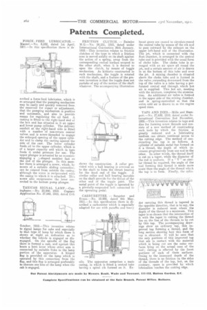
TAPS AND DIES.—Mille and Stempert.—No. 27,630, 1910, dated under International Convention 2nd December, 1909.—This invention relates to taps and dies for forming screw threads and consists of a new method of constructing such tools by which the friction is greatly reduced and a lubricating medium can obtain continual access to the cutting edge. The method of constructing the tap is as follows. A cylinder of suitable metal has formed on it a thread, the depth of which increases progressively from one end to the other. In other words, the thread itself is cut on a taper, while the diameter of the rod is uniform. If a " V" or similar thread be required, the angle of the tool forming this thread is made more acute than the angle of the thread which the tap is to form. Finally, the cylin der carrying this thread is tapered in the opposite direction, that is to say, the diameter is reduced most where the depth of the thread is a minimum. This taper is so chosen that the intersection of it with the taper in cutting the thread lies on the line of the threads to be cut by this tap. The accompanying drawings show an ordinary tap, this improved tap forming a thread, and the long section showing how this form of tap is obtained. It will be seen that the only portions of this improved tap that are in contact with the material which is being cut are the outer surfaces lying on the actual cone of the took ; cutting is effected by the front portions of each of these surfaces. Owing to the increased depth of the thread, there is no friction on the sides of the threads of the tap, but, on the contrary, space is provided by which lubrication reaches the cutting edge.