


The Technicalities of MODERN GEAR OX DESIGN
Page 50
Page 51
Page 52
If you've noticed an error in this article please click here to report it so we can fix it.
By A. W. HAIGH A.M.I.Mech.E.
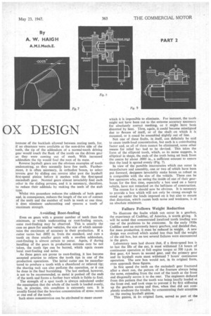
QUIETNESS of operation and even tooth loading are dependent on many contributory factors, but a short study of tooth action will be of great assistance in its simplification. The involute ..urve has been standardized as the tooth form 13 be used in automobile gears because it provides constaet-speed transfer from one gear to another, and is comparatively easy to produce.
It is generated, simply, by a piece of string, which is unwound from a circle. If, while the string is being unwound from one circle it be wound on to another, the speeds of revolution will be constant and relative in value, proportional to the diameters of the two circles. Involute teeth raised en these circles, known as the base circles, always contaet each other at points lying on the connecting piece of string (Fig. 5), the string being known as the line of action. The angle between the line of action and a line perpendicular to that joining the gear centres (0, P in Fig. 5) is the pressure angle
Now, consider exactly what occurs as two teeth contact each other for the full length of the line of action. When contact is first made (refer to Fig. 5), the tooth on wheel. A is moving in two directions, that is, around the periphery and downwards in a direction from the centre of wheel A to that of wheel B. Similarly, the tooth on wheel B moves around its own circle, and towards the centre of wheel A.
Thus, in addition to any rolling which takes place between the two teeth, there is also considerable sliding, which continues unti. the point of contact reaches the intersection of the pitch circles with the line joining the gear centres. As the point of contact leaves this intersection, sliding begins once more, but in the opposite direction, that is, the tooth on A travels towards the centre of its own gear, whilst that on B travels towards the centre of wheel B.
Gear-tooth Finish
No matter how well a machined surface may be finished, there is still a number of minute protrusions on it, the height of which is often sufficiently great to extend beyond any oil film which might be trapped between two such surfaces as two gear teeth. Sliding between these surfaces, as already described, is bound to cause rough and noisy operation, the magnitude of which is governed by the smoothness of finish, always assuming that a true curve has been maintained for the tooth profile. If the surface of one tooth be likened to a cobbled road, and that of the other to a stick, knowing that pushing the stick produces far more resistance than pulling it along the road, it can be appreciated that when the teeth are approaching the centres of their opposite gears, namely, pushing, the resistance and roughness are at a maximum.
There are two possible remedies for this cause of noise, one being to lap all teeth to the finest possible finish, a
process which would prove extremely expensive in production, and the other to shorten the period of time during which pushing betwe-n the sliding teeth occurs, or to shorten the distance ot the pushing.
An examination of Fig. 5 shows that contact between two teeth first occurs at the extreme tip of the addendum of the driven gear and in the root of the driving gear, and pushing—or to be mire technical, approach—occurs for the length of the driven-gear addendum when recession starts. If, therefore, the addendum of the driven gear be reduced in length, the period of approach must be reduced, and noise and toughnesS decreased to a minimum.
This correction is carried out on many gears, in addition to which the addendum of the driven gear is increased in order that the full amount of tooth contact, approach plus recession, cac be assured.
The increasing and decreasing of addenda was not, however, first introduced to improve gear action by the reproportioning of the arcs of approach and recession, but was devised to counteract undercutting on gears with only a small number of teeth.
The involute curse on the profile of a tooth extends from the tip to the base circle only (Fig. 6). Below the base circle the tooth is finished with a straight radial line. On gears with a small number of teeth, the distance from the base circle to the pitch circle is smaller than the addendum of the mating tooth. Hence, as involute action occurs only above the base circle, action between the tip of the mating gear and the straight line below the base circle, on the tooth in question, will be something other than what is required. In fact, teeth on small-denomination gears, if generated in a normal milliner are all subject to undercut below the base circle.
Features Governing Undercut
The amount of undercut is regulated by the number of teeth in the gear, and their pressure angle. The more teeth there are, the less the undercut, because, as the number of teeth increases, the distance between the base circle and the pitch circle also increases, so that when the base circle falls below the root circle, the tooth profile becomes entirely involute.
As the pressure angle increases, undercut decreases. Taking two teeth, both on 17-toothed gears, one, having a pressure angle of 20 degrees, will show no appreciable undercut, whilst the other, having a pressure angle of 18i,degrees, will be markedly undercut.
If we imagine this second tooth to have the conventional straight flank, then any mating tooth must tend to dig into it below the base circle. If, on the other hand, the tooth be generated with the undercut, its strength is considerably impaired at what should be the most robust section.
In order to obviate both these disadvantages, the addendum of driven gears can be reduced and that of driving gears increased. The latter is permissible only because of the backlash allowed between mating teeth, for, if no clearance were available at the non-drive side of the teeth, the tip of the addendum of a normal-tooth driving gear would touch the flank of the tooth on the driven gear as they were coming out of mesh. With increased addendum the tip would foul the root of its mate.
Reverse layshaft gears are the obvious examples of tooth undercutting, as they normally have few teeth. Furthermore, it is often necessary, in orthodox boxes, to select reverse gear by sliding one reverse idler past the layshaft first-speed pinion before it meshes with the first-speed mainshaft gear. Normal gears almost invariably foul each other in the sliding process, and it is necessary, therefore, to reduce their addenda by making the teeth of the stub type.
Whilst this procedure reduces the addenda of both gears and, in consequence, reduces the length of the arc of contact of the teeth and the number of teeth in mesh at one time, it does eliminate undercutting and ensures a tooth of maximum strength.
Avoiding Root-fouling
Even on gears with a greater number of teeth than the minimum, at which undercutting or root-fouling occurs, some root-fouling may be observed. This is usually the case on gears for smaller vehicles, the size of which necessitates the maximum of accuracy in their production. If a cutter varies but .0002 in. from the standard, and cuts a tooth on these smaller gears with a swollen addendum, root-fouling is almost certain to occur. Again, if during handling of the gears in production extreme care be not taken, the tooth tips can be burred, which again causes local root-fouling and noise.
As these gears are prone to root-fouling, it has become accepted practice to relieve the tooth tips in one of the production operations. The initial cutter can be manufactured to produce a tooth with a chamfered or relieved tip; the shaving rack can also perform the operation, or it can be done in the final burnishing The last method, however, is not to be recommended, as metal is pushed off the ends of the teeth and forms a further burr which is liable to foul.
The strength of a spur tooth is always calculated under the assumption that the whole of the tooth is loaded evenly, but, in practice, this condition is extremely rare. It is usually found that the heaviest concentration of stress .occurs at one end of the tooth.
Such stress concentration can be attributed to many causes which it is impossible to eliminate. For instance, the tooth might not have been cut to the extreme accuracy necessary for absolutely correct meshing, or it might have been distorted by heat. Then, again, it could become misaligned due to flexure of itself, or of the shaft on which it is mounted, or it could be assembled slightly out of line.
Not one of these faults, in itself, can definitely be said to cause tooth-load concentration, but each is a contributing factor and, as all of them cannot be eliminated, some other means for relief has had to be devised. This takes the form of the elliptoid tooth, which, as its name suggests, is elliptical in shape, the ends of the teeth being set back from the centre by about .0005 in., a sufficient amount to ensure that the load is spread evenly (Fig. 7).
In view of the possible inaccuracies which can occur in manufacture and assembly, one or two of which have been put forward, designers invariably make boxes as robust as is compatible with the size of the vehicle. There can be few operators who, on seeing the inside of one of their gearboxes for the first time, especially a box used on a heavy vehicle, have not remarked on the heftiness of construction.
The reason for it should now be obvious. It is necessary to provide a box which will not only be strong enough to stand up under the loads imposed on it but also to ensure that distortion, which causes both noise and weakness, is at an absolute minimum.
• Failure Follows Weight Reduction
To illustrate the faults which can occur in a gearbox, the experience of Cadillac, of America, is worth giving. It will be noted that concentrated localized tooth loading was one of the problems to be overcome. In the early 1930s Cadillac used an extremely heavy gearbox, and decided that, for mass production, it must be reduced in weight. A new design was evolved which scaled less than half the weight c; the old box, but on test several failures were encountered in the gears. Laboratory tests had shown that, if a three-speed box is to last the life of the car, it must withstand 2.6 hours of continuous operation at full engine torque at 500 r.p.m. in first gear, 4.4 hours in second gear, and the primary gear and its layshaft mate must withstand 7 hours' continuous operation. The new box would not, in its original form, even approach these figures. In first speed the teeth on the mainshaft gear fractured after a short run, the pattern of the fracture always being the same, extending from the root of the tooth at the front end diagonally across it to the rear. The engineers deduced from this pattern that the tooth was being locally loaded at the front end, and took steps to prevent it by first stiffening up the gearbox casing and then, when that did not completely eradicate the trouble, by concentrating their attentiOn on the mating layshaft pinion. This pinion, in its original form, served as part ot the reverse train, and the first-speed train, the reverse idler gear and the first-speed gear working side by side, which necessitated an exceptionally long layshaft pinion, the teeth of which did not allow sufficient yield at the first-speed end. When a groove was cut in the middle of the teeth and a new bearing area arranged by relapping, the fault was entirely eliminated, so that the gear worked much longer than the prescribed 2.6 hours without failure.
In second gear, failure of the layshaft pinion was experienced, the fracture always starting at the sharp forward end of the helical teeth, again pointing to uneven tooth loading. When the pinion tooth was lengthened so that it overlapped the driven gear, further failures were tiot encountered.
Primary Shaft Weakness
Of the two constant-mesh gears, the primary gear and its layshaft mate, the latter failed in the same way as the second-speed layshaft pinion, but lengthening the tooth, whilst preventing further breakage on the layshaft gear, caused the teeth in the primary gear to fracture. Eventually, the cause of these failures was attributed to a weak primary shaft, and on stiffening this member the entire transmission operated satisfactorily.
One of the most urgent complaints against normal gearboxes by drivers, especially those with little experience, is the difficulty experienced in changing down. At the risk of stating the obvious, I will explain the reason.
Imagine a machine, fitted with a " crash-type " box, to be travelling along in top gear, and that it is necessary to change down to third speed. In top gear, the primary shaft is coupled directly to the mainshaft and so to the rear axle by the third-speed mainshaft gear, which has been slid up to it, and the internal dog teeth in the third-speed gear coupled to the external teeth on the primary gear, as shown in Fig. 8.
In order that third gear may be engaged, the third-speed mainshaft gear must be slid along its shaft until it meshes with pinion A on the layshaft. Assume, for argument's sake, that the ratio of the constant-mesh gears, B and C, is 2 to 1. Then, while top gear is engaged, the third-speed mainshaft gear, D, is revolving twice as fast as pinion A, with which it must be meshed for third gear. So, if D be slid out of contact with B, and attempts made to mesh it immediately with A, grinding is bound to occur.
Synchronizing Peripheral Speeds
To make a smooth change, it is necessary to synchronize the peripheral speeds of the gears. Either the revs, of gear D must be reduced, or those of pinion A increased. As there is no means for slowing down D, except by applying the brakes, A must be speeded up by putting the gear in neutral and revving up the engine.
To obviate the necessity of double-declutching in order to synchronize gear speeds, synchromesh mechanisms were invented. They take two main forms—the constantpressure type, and the inertia-lock pattern.
The more simple constant-pressure type is illustrated in Fig. 9, A being the gear which it is desired to connect to the mainshaft. Sleeve B is splined on its inner surface so that it can mesh with both the dog teeth on gear A and the outside splines on hub C. Hub C is free to slide on the mainshaft and is held integral with sleeve B by means of the spring-loaded balls,. one only of which is shown.
When the two parts. B and C, are moved towards gear A, the conical recess in C. comes into contact with the cone on A, and acts as a friction coupling or brake. This eventually causes gear A to totate at the same speed as the mainshaft, and a little extra pressure on the change-speed lever frees B from C, by overcoming the spring pressure, and allows it to slide into mesh with A.
The constant-pressure type of synchromesh mechanism has one big disadvantage in that it is still possible to grind the gears. If too great a pressure be applied to the gearlever knob, the spring loading, holding parts B and C together, is overcome at once, and B attempts to engage with A before synchronization has taken place. With the inertia-lock type, however, no gear grinding is possible.
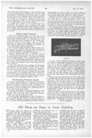
A section through a Warner synchronizer, which works on the inertia-lock principle, is shown in Fig. 10. It consists of a hub, A, fixed to the mainshaft, on which slides a collar, B. Jn the hub periphery are three slots in which shifting plates slide, the plates having a raised portion at their centres which is held in a groove in the sliding collar, B, by means of two expander springs, C. Blocker rings, 'D, are mounted on both sides of hub A, being formed conically on their inner surfaces, and are held in position by face lugs which register in the shifting-plate slots in the hub.
The face tugs are narrower than the slots so that, when the sliding collar is moved to select a gear, the blocker ring comes into contact with the cone on the gear and is displaced by it to one side of the slots. As the blocker ring has teeth on its outer periphery, these become misaligned with the internal teeth on the sliding collar, so that, no matter what pressure be exerted on it, it is impossible to effect engagement with the dog teeth on the gear until synchronization between the gear and the synchronizer assembly takes place.
When the gear has been slowed down by the braking effect of the cones, or when the speed of the synchronizing mechanism has been increased by the same means, there comes a time when the blocker ring moves back across the shifting-plate slots until its teeth line up with those on the sliding collar. Engagement of the gear then takes place.