


TRANSMISSION IMPROVEMENTS.
Page 30
If you've noticed an error in this article please click here to report it so we can fix it.
A Résumé of Recently Published Patents.
A new arrangement of the tiatismission gear for electric vehicles is described in Patent Specification No. 178,001, by H. Woods and another. It
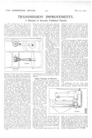
analogous to that form of transmission in a petrol-driven chassis which embodies a combined torque and radius rod which serves to enclose the propeller shaft, being anchored at its rear end to the live axle casing and at the fore end to the gearbox. In the case of the mechanism described in this specification, however, the further advantage is presented that the need for unusual joints is eliminated.
No gearbox is employed whatever, the motor driving the propeller shaft. through a pair of bevel gears. Three different arrangements of the mechanism are covered by the patent. One, that to which we make particular reference here, refers to a chassis wherein only one driving motor is used. The second deals with a vehicle for driving which two motors are connected to a common propeller shaft, the third with a form in which, again, two motors are erriployed, hut in which the differential gear is eliminated, each motor driving its, own wheel through its own propeller shaft and reducing bevel gears, the propeller shafts themselves being conee»trii,a the outer one tubular and the other mounted therein. The features covered by the patent are the same in each,
Referring to one of our illustrations, the motor is arranged at a convenient distance from the rear axle, so that. the propeller shaft casing may be of reasonable length, considered as a radius and torque rod. It is located towards one side of the chassis, and the inner end of its armature shaft carries a bevel pillion which engages a wheel on the for. ward end of the propeller shaft. The latter is contained within a taper sleeve or casing Of the usual form, bolted at the rear end to the axle case, and having a parallel turned fiat at its fore end which bears in a suitable bored hole in a T-shaped. casing surrounding the bevel driving gears. This disposition of the torque tube allows of one rear wheel
C30 being elevated above the other, the tube turning within its bearing accordingly.
The T-shaped casing is supported through a pair of bearings formed, as it were, in the flange of the T, and carried at one side on a spigot formed in tho motor casing itself, and at the other upon a similar projection On a special bracket which is bolted to the two crossmembers Of the chassis frame upon which the motor itself is bedded. Freedom or vertical
movement of the \ axle, under the combined influence of springs and road, is thus afforded.
The propeller shaft is supported within the casing by ball hearings, of which that at the forward end is mounted with in the recessed outer face of a nut. which bears upon the fore end of the tubular easing. The latter is located longitudinally by this nut and by two others, of which one is a lock-nut, which bear against the rear end of the T-shaped casing. By manipulation of these f the depth of engager of bevel gears can be
Other Patents of Interest.
No. 178,002 is also in connection with transmission gear, and describes a design of gearbox. The main casting is cylindrical, open at both ends. The covers for these ends are made exactly alike, each having formed thereon all the necessary bosses for main, lay arid reverse shafts, and for selector reds, etc., so that either cover will do for either end of thc. box. Only thoso bosses which are actually required are machinedThe patentee of this gearbox is G. Funck.
G. Loveridge invents a bevel-typo differential gear in the engine flywheel. One sun wheel of this gear is coupled to the propeller shaft of the car, the other, by chain gearing, to a pump. By control of the inlet and outlet apertures of the pump, resistance to movement of the one sun wheel is adjusted, with corresponding variation of the rate of revolution of the other. An infinitely variable gear is tints attained. The mechanism is described in Specification No, 177,981.
The principal object which J. D. Sid'
deley has in view, in the motorcar construction which he describes in No. 177,857, is that. of increasing the general field of Utility of the vehicle. There are provided seats for three, of which the centre one—the driver's—is permanent, the others being of the. hammock type and designed to roll up out of the way, tho space thus rendered available being adapted for the conveyance of baggage or of Merchandise made up in the form of parcels.
In. the cooling system, which is the subject of No. 154,935, by W. W. Muir, the circulating water pipe is enlarged to such an extent as to form a reservoir of capacity equal to that usually afforded by the radiator itself. The latter, in this system, functions only ass condenser, to deal with any steam which may he formed. The water itself is pumpcirculated through the pipes only, being maintained, while the engine is running, at boiling point. Provision is made for the return into circulation of any steam which is condensed by the radiator.
An ingenious method of controlling the amount of heat which may be tranaferred from exhaust to inlet manifolds is described in No. 178,023 by Humber, Ltd. Its operation is dependent on the principle that the transfer is proportioned to the area of surfaces in contact, and the heat transmission controlled, in a simple manner, by altering the area of those surfaces, A flange is formed on each pipe, their 'disposition being such that a block of metal may slide between them. The block is slated so that it is nearly split, and a bolt-operated wedge is used to widen the slot, ensuring proper contact of the faces, and at the same time holding the block in any desired position.
F. Reddaway and Co., Ltd., have • evolved a solid tyre which is detachable and of greater resilience than the usual
type. It is not, vulcanized on to a steel band, but is backed by canvas, its base being corrugated in form, the convex portions resting on the rim, the concave parts bearing upon rollers of soft rubber, which are gripped between the two detachable flanges of the wheel rim. Alternative construction, as well as that to which reference is made above, are described in Specification No. 177,999.