


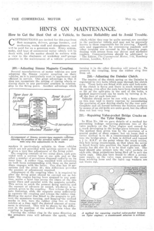
209.—Adjusting Simms Magneto Coupling.
Page 28
If you've noticed an error in this article please click here to report it so we can fix it.
Several manufacturers of motor vehicles are now adopting the Simms vernier coupling on their vehicles, as it, is particularly neat in appearance and efficient in service. One great advantage is that it does not necessitate the setting of timing wheels or timing chain in any particular position in relationship to the firing point. Another advantage which
renders it particularly suitable to those vehicles which are not provided with ignition control is that it gives a very fine adjustment tif the firing point. The coupling consists of two metal discs, each provided with a central boss. at one side and at the other a number of serrations disposed radially on its inner face. A rubber ring, moulded with serrations on both faces corresponding with those on the metal discs, engages with the latter. One disc has 19 serrations and the other 20; this difference provides the amount of adjustment required. Adjustment of the coupling when it is required 'to alter the firing point should be carried out as follows: The engine having been stopped'in any position, scribe a faint line across the edges of the two metal discs and parallel with the magneto spindle. This serves to mark the present firing position and the amount of advance or retard, whichever is 'required, given to the coupling. Now release the magneto fastening, slide the magneto away sufficientl3r to separate the coupling and release the rubber ring. Holding the metal disc fitted to the magneto to prevent the armature turning, and keeping-the scribed marks in line, turn the rubber ring two or three notches at a time until the desired amount of movement is obtained. This will be shown by the difference in the position of the scribed lines when the coupling is together.
Turning the rubber ring in the same direction as the armature runs will advance the spark, whilst a2P turning it in the other direction will retard it. To preserve the coupling, keep the rubber ring free from oil.
2111—Adjusting the Daimler Clutch.
The tension of the clutch spring on the Daimler is regulated by two bolts which pass through the clutch cone. These bolts are fitted with nuts and lock-nuts. If the clutch is fierce and there is much tensionon the spring, even after the nuts have been slacked back so far as the split-pins in the end of the bolts, a marked improvement can be made by turning Ili off the face of each lock-nut.
Vehicles should never be run with a fierce clutch, as this may lead to heavy expense by necessitating the provision of new driving shafts for the rear axle. Graphite and oil forced between the friction surfaces by means of an old knife are quite good, but the effect does not last very long
211.—Repairing Valve-pocket Bridge Cracks on the Tylor Engine
In Hint No. 190 we gave details of a, method for preventing leakage occurring .between two of the valve pockets on the Tylor engine and caused by a crack developing in the bridge-piece between them. The method then given was by the provision of a special gasket of sheet copper, but we learn that a. better method is to fit a countersunk-beaded screw into the bridge-piece. A hole is drilled and tapped a in. B.S.F. at the point where the crack .occurs, this hole being countersunk, so that when the screw is fitted firmly into in the head projects sufficiently for the slot n it to be filed right out. The head should also project into the valve pockets on each side, these projections being filed off to suit the valve caps. This has been found-to effect a permanent repair, as the valve caps prevent the screw from working loose and the valve cap washers are not blown out.