


Patents Completed.
Page 20
If you've noticed an error in this article please click here to report it so we can fix it.
Challiner Built-up Road Wheels. Engine,-Starting System. Improved Differential Gear. An Interesting Gearbox Design.
Copies of complete specifications of the patents"published on this page can be obtained from the Sales Branch, Patent Office,. Holborn, W.C., at the cost of sixpence for each specification.
J. E. EVANS-JACKSON, No. 10,511, dated 20th July, 1915.— In this gear the driving shaft is provided with a driving-disc which carries round with it a number of intermediate shafts. On these shafts are gearwheels which may for convenience be called planet wheels, although the gear is not in the strict sense epicyclic. A sun wheel on the driven shaft meshes with the planet wheels, and is driven by them.
Each intermediate shaft carries a crank arm at one end, which is periodically oscillated b,17, a fixed cam. A friction clutch serves to lock each intermediate shaft to its planet wheel, and is brought into engagement by a screw device just at the time when the shat is being oscillated, so that the oscillation of the shaft rocks the planet wheel and thus causes it to drive the sun wheel of the gear. When the effective drive due to the oscillation is completed, the clutch on that shaft is thrown out, but the gear on the next shaft is just craning into action so that the drive is continuous.
The screw device on each intermediate shaft which works the friction clutch is controlled by an arm which presses against a surrounding controlling cam, By circumferential movement of this cam the part of the rotation at which the clutching is effected is varied, so that clutching takes place at a time when the oscillatory movement of each of the intermediate Shafts, is either, say, at its maximum rate in one direction, or at a less speed, or in the reverse direction. The speed may thus be varied or reversed.
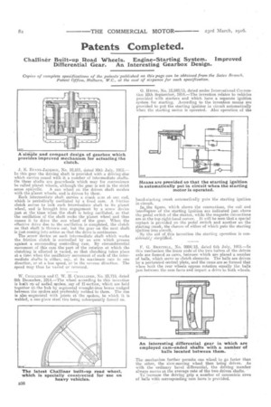
W. CIIALLINER and C. W. II. CIIALLINER, NO. 23,718, dated 8th December, 1914.—The wheel according to this invention is built up of ra,clikil spokes, say of 1f-section, which are held together at-the hub by segmental wrought-iron boxes wedged between the spokes_ and preferably welded to them. The rim is also segmental with joints at the spokes, to which it is welded, a one-piece steel tire being subsequently forced on. 0. HEiNs, No. 12,248/15, dated under International Convention 10th September, 1914.—The invention relates to vehicles provided with starters and which have a separate ignition system for starting. According to the invention means are provided to put the starting ignition in circuit automatically when the starting motor is operated. Also operation of the hand-starting crank automatically puts the starting ignition in circuit.
in,the figure, which shows the connections the • coil and interrupter of the starting ignition are indicated just above the pedal switch of the starter, while the magneto connections are at the top right-hand corner. It will be seen that a special contact is provided On the pedal switch and another ou the starting crank, • the closure of either of which puts the starting iNition into circuit, . By the aid of this invention the starting operation is considerably simplified.
F. G. BRETTELL, No. 9804/15, dated 6th July, 1915.—In this mechanism the inner ends of the two halves of the driven axle are forrmti as cams, between which are placed a number of balls, which serve as clutch elements. The balls are driven by is perforated central plate, and the earns are so formed that when both the rear wheels oppose rotation equally the balls jam between the cam faces and impart a drive to both wheels.
The mechanism further permits one wheel to go faster than the other, the slow-moving wheel then being driven. As with the ordinary bevel differential, the drivingmember always moves at the average.rate of the two driven shafts. ' To increase the driving grip a number of concentric rows of balls with corresponding cam faces is provided.