Brake Equalization in Articulated Vehicles
Page 36

If you've noticed an error in this article please click here to report it so we can fix it.
A Résumé of Patent Specifications That Have Recently Been Published
A CCORDINQ to patent No. 553,373, rlit is generally desirable with a tractor trailer outfit to arrange that all the brakes be applied at the same time, but that the braking effort on the trailer wheels should be about double that on those of the. tractor unit. The patentee, I3endix Aviaton Corporation, South Bend, Indiana, U.S.A., describes a control valve in which this effect is produced with the addition of an adjustment by which the excess braking effort on the trailer can be varied within wide limits.
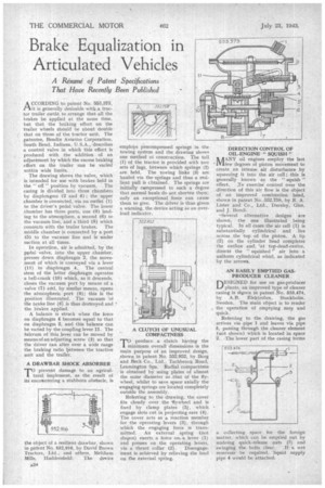
The drawing shows the valve, which is intended for use with brakes held in the " off " position by vacuum. The casing is divided into three chambers by diaphragms (2 and 4) ; the upper chamber is connected, via an outlet (I) to the driver's pedal 'valve. The lower chamber has three ports, one (9) leading to the atmosphere, a second (6) to the vacuum line, and a third (8) which connects with the trailer brakes. The middle chamber is connected by a port (5) to the vacuum line and is under suction at all times.
In operation, air is admitted, by the pedal valve, into the upper chamber, presses down diaphragm 2, the movement of which is conveyed via a lever (1I) to diaphragm 4. The central stem of the latter diaphragm operates a bell-crank (10) which, as it descends, closes the vacuum port by means of a valve (7) arrd, by similar means, opens the atmospheric port (9); this is the position illustrated. The vacuum "of the brake line (8) is thus destroyed and the brakes applied.
A balance is struck when the force on diaphragm 4 becomes equal to that on diaphragm 2, and this balance can he varied by the coupling lever II. The fulcrum of this lever can be moved by meansof an adjusting screw (3) so that the driver can alter over a wide range the braking ratio ljetvveen'the tractive unit and the trailer,
A DRAWBAR SHOCK ABSORBER
rro prevent damage to an agricultural implement, as the result of its encoantering a stubborn obstacle, is the object of a resilient drawbar, shown in patent No. 552,916, by David Brown Tractors, Ltd., and others, Meltham Mills, Huddersfield. The device
employs precompressed springs in the towing system and the drawing shows one method of construction. The tail (1) of the tractor is provided with two sets of lugs, between which springs (2) are held. The towing links (3) are hauled via the-springs and thus a resilient pull is cbtained. The springs are initially c*mpressed to such a degree that normal hauls do not shorten them; only an exceptional force can cause them to give. The driver is thus given a warning, the device acting as an overload indicator.
A CLUTCH OF UNUSUAL COMPACTNESS
TO produce a clutch having the minimum overall dimensions is the main purpose of an improved design, shown in patent No. 552,952, by Borg and Beck Co., Ltd., Tachbrook Road, Leamington Spa. Radial compactness is obtained by using plates of almost the same diameter as that of the flywheel, whilst to save space axially the engaging springs are located completely outside the assembly.
Referring to the drawing, the cover fits closely over the 'flywheel and is fixed by clamp plates (a), which engage slots cut in projecting ears (4). The cover acts as a reaction member for the operating levers (3), through which the engaging force is transmitted. An external spring (not shcavn) exerts a force om a lever (1) and presses on the operating levers, via a thrust collar (2) Disengagement is achieved by relieving the load on the external spring.
DIRECTION CONTROL OF OIL-ENGINE "SQUISH
NAANY oil engines employ the last I.Y.Lfew 'degrees of piston movement to create an intense air disturbance by squeezing it into the air cell; this is generally known as the " squish " effect. ..To exercise control over the direction of this air flow is the object of an improved combustion head, shown in patent No. 552,758, by R. A. Lister and Co., Ltd., Dursley, Glue, and J. Bondi.
--Several alternative designs are shown, the one illustrated being typical: In all cases the air cell (1) is substantially cylindrical and lies across the -top of the piston. A. lip (2) on the cylinder head completes the outline and, ?at top-dead-centre. directs the " squished " air into a uniform cylindrical whirl, as indicated by the arrows.
AN EASILY EMPTIED GAS. PRODUCER CLEANER
DESIGNED for use on gas-producer plants, an improved type of cleaner casing is shown in patent.No. 553,474, by A.B. Elektrolux, Stockholm, Sweden. The main object is to render the operation of emptying easy and quick.
Referring to the drawing, the gas arrives via pipe 1 and leaves via pipe 5, passing through the cleaner element (not shown) which is located in space 2, -The lower part of the casing forms a collecting space for the foreign matter, which can be emptied out by undoing quick-release nuts (3) and swinging the bolts clear. If a wet reservoir be required, liquid supply pipe 4 Nvould be attached,


