


Reducing Transmission Shocks
Page 68
If you've noticed an error in this article please click here to report it so we can fix it.
A New Borg and Beck Clutch Incorporating a Shock-damping Device and a Driven Plate with a Flexible Periphery. ,
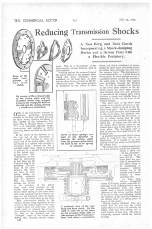
By means of the crimped edge of the driven plate and the moulded rubber ring, gripped between the triangular boss on the hub and the casing, driving 2 shocks are minimized.
ONE of the best-known concerns in America marketing proprietary clutches is the Borg and Beck Co.,*and its latest model, recently introduced to this country by the Automotive Products Co., 3, Berners Street, London, W.1, is of ingenious, although simple, construction and embodies a shockabsorbing device mounted on the driven plate.
In the centre of the flywheel, or in the rear end of the crankshaft, is mounted a ball bearing to carry the spigot end of the clutch shaft. On the last-named is a splined hub carrying a triangular body. Around this fits a moulded rubber ring, which is retained in position by a pressed housing fixed to the driven plate by nine rivets. The construction of this plate is interesting in that there are 12 T-shaped slots in its periphery, The portions of the plate , between the slots are bent to form spring blades, six , pressing outwards and six inwards.
The two friction facings are riveted
to the periphery of the driven plate, each being retained by six rivets ; these pass through alternate blades which spring in the same direction, thus ensuring that the friction facings are not deformed when the blades flatten as the clutch takes up the drive. This construction results in the friction facings being separated by the action of the spring blades of the plate periphery when not under load. As the clutch pedal is released the pressure plate forces the driven member against the face of the flywheel and the " crimped " edges of the driven plate flatten, thus ensuring smooth engage
I
levers, and clutch withdrawal is accomplished by their inner ends being moved forwards, thus releasing the load from the pressure plate. The last-named is moved backwards, i.e., is freed from the driven plate, by three springs located at equidistant points around the periphery, the outer ends of which 'abut against pins projecting through the flywheel rim. It will be realized that rotation of the cover plate relative to the flywheel carries the three arms around, thus bringing them into new positions on the cams of the pressure plate, which provides a simple and reliable form of adjustment to take up the wear of the friction facings.
The inner ends of the three arms operate in an annular groove in a central sleeve, which is keyed to the flywheel cover plate. The key permits the sleeve to move forwards and backwards in the -cover plate, but prevents relative rotation between the two parts. A . coil or volute spring may be used, according to the available space in the clutch pit. In either case the ends of the spring abut against faces on the central sleeve and on the exterior of the cover plate. The last-named. part is held in place by three dogs bolted to the flywheel rim.
A graphite-impregnated clutch-release collar is employed ; this calls for no lubrication. It is housed in an iron casting which has arms to accommodate the release fork.
The clutch sizes available immediately are 9 ins, diameter and 10 ins, diameter.
whilst a third size —11 ins, diameter— is expected to be
here shortly. The three sizes are capable of transmitting any power likely to he encountered in passenger vehicles seating up to 20 persons and in goods vehicles of corre i sponding size.
In these days,
T‘,
when mechanical silence is so highly prized, especially for passenger work, anything which can reduce transmission noise and shock should meet a steady demand. The lightness of the driven member should be an aid to easy gear-changing, whilst the abolition of the need for lubricating the release collar is a strong point in favour of the design.
Should surplus lubricant from any source find its way into the clutch centre there is no fear of it reaching the rubber ring and thus giving rise to rapid failure of that part. The ring is completely encased behind the pressed housing.