


New Clarkson Automatic Coke-fired Lorry.
Page 9
Page 10
Page 11
Page 12
If you've noticed an error in this article please click here to report it so we can fix it.
First-published Descriptive Details of a Steam-propelled Three-tonner which may lead to Remarkable Developments in the Industry.
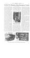
It is with much pleasure that we find ourselves in a position to place before our readers full particulars of a new type of machine which points to remarkable developments in the field of industrial-vehicle pro duction. It is a three-ton automatically coke-fired steamer, manufactured by the National Steam Car Co., Ltd., of Chelmsford, and Mr. Thos. Clarkson, M.I.C-.E., M.I.M.E., etc.., managing director of the company, is responsible for its intro duction. We previously referred to this development in our issue dated 14th May last.
As is very well known, Mr. Clarkson has done much towards the perfecting of the steam-driven motorbus, and the familiar white National steamers, which are running so successfully in London and certain parts of the Provinces, testify that his experience in this direction stands pre-eminent.
The Chief Aims of the Designer.
In building this solid-fuels-fed three-tonuer the chief aim of the constructor has been to produce a goods-carrying machine of comparatively light build, which shall be highly efficient in service, easy to handle, and, what is a most determining factor, a vehicle which is quite independent of petrol or petrol substitutes for its motive power. We find that the builder has marketed what is undoubtedly a remarkably simple, coke-fired lorry, and an equipment which 1should prove efficient and economical in service. He has combined all the best points which a complete knowledge of the problem has placed at his disposal.
For the purpose of securing exhaustive particulars of the construction we journeyed last week to Chelmsford, and after a lengthy trial run on one of the new lorries, .a thorough inspection of a stripped chassis was carried out and a series of interesting photographs
seemed, many of which w e herewith reproduce.
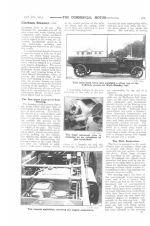
The steam generator which feeds the horimmital two-cylinder engine on these vehicles may be fired either with liquid fuel, such as kerosene, or with solid fuel in the form of graded cokeThe particular chassis under consideration, which is now a standard type, is designed to use the latter class of fuel, and it must be admitted at the outset that coke is frequently the cheapest form in which to buy units of heat.
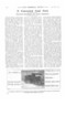
One objection, however, to its use in this direction has been that it usually necessitated stoking by hand. the tendency being for clinkers to form, thus obstructing the draught which is so essential to produce the best results. With hopper stoking there has been difficulty in obtaining a regular feed to the fire, owing to the coke jamming. These difficulties, however, have been overcome in the National coke-fired chassis in a simple and
most practical manner. We herewith produce a sectional line-drawing of the generator, together with the coke feeders ; the manner in which the component is mounted
on the rolled-steel frame of the chassis is also clearly shown.
It will be seen that time boiler consists primarily of a steel central drum into which are expanded solid-drawn steam generating tubes. The teed-water which enters the drum is suitably preheated first by the main exhaust, the pipe of which is led direct from the engine through the water tanks, after which it passes through a nest of coiled tubes which are super-imposed over the horse-shoe-shaped generating tubes. The steam before it enters the engine, is heated
to a high tel super.heating coils for the purpose being placed in close proximity to the tire.
The working steam-pressure is 300 lb. per sq, in..; before being fitted into the chassis each boilet is tested to a pressure of 700 lb. per sq. in. We found that the generator holds steam exceedingly well, witnessing this for ourselves by mounting the lorry in the works yard about three hours after our morning run, when the needle of the steam-gauge had hardly perceptibly altered its position. The beating surface of the
generator is 51 sq. ft. It is designed to take either upward or downward draught., no chimney being needed in the latter case. The coke bunker is built in with the generator, and the whole, as a unit-, is mounted on the chassis immediately to the rear of the front axle. There are two large-sized doors on each side of the boiler housing, the top one in each case being used for the charging of fuel, and the lower one for providing free access to the combustion chamber and coke feeders.
The first illustration below shows a superheater unit on the ground. There is no fan fitted, but the large vertically-gilled-tube condenser, which is a distinctive feature at the forward end of the chassis, is found quite efficient for all conditions of working, The boiler feed-pump is designed to work in conjunction with the coke-feeder, the apparatus being mounted on the near side of the eintssis in a very accessible posit:on ; there is an additional set of cake-feeders placed on the righthand side of the boiler. The pump and feeders are driven independently of the main power-unit, and there is a graduated disc and pointer fitted which enables fuel and water to be supplied according to the amount required. The water-pump and coke-feeders may be actuated by hand.
The High-.speed Engine.
As we before stated, a twocylinder engine is fitted, the bore and stroke respectively being 4 ins. by 4 ins. ; the power unit is double acting. The Joy form of valve gear which is fitted is wholly enclosed in a light oil-tight easing. Advantage is taken of the expaneiVe properties of steam by providing for a -cut-off of about threeeighths of the piston stroke. There are two notches for linking tip, the control lever for this and for reversing being placed to the righthand side of the driver's seat, in the position usually occupied by the change-speed lever on a petroldriven motor.
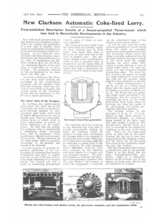
Herewith we reproduce a sectional drawing of the power unit ; on reference to this it will be seen that all the main bearing surfaces are ample, and that the marine type of connecting rod is a particularly sturdy job.
The engine and oil pumps, as a unit, are located just a little to the tear of the driver's seat ; they are fitted quite low in the chassis ; fact, right throughout the whole length of the latter there are no projections ef any kind to interfere with the body platform. The steam and oil glands are readily get-atable.
Accessibility a Feature.
The whole of the reciprocating parts can, if necessary, be removed from the engine-case without taking the latter down from the chassis. There are three large sized doors fitted for the purpose, all the valve mechanism being
mounted on the lower cover. The crankshaft runs on two large bear ings, and these are supplied with lubricant by the aid of an oil pump of the rotary-gear type ; this, together with the force-feed pump which supplies the cylinders with the necessary lubricant, is driven by a worm machined on an exten.. sion of the engine shaft. The engine is carried on the three-point-suspension system, and we noticed that there is the minimum of overhang. Its supoort takes the form of two arms which are steel stampings, and which are bolted directly to the centre and base respectively of the engine, whilst the supporting arms themselves are in turn clamped to two transverse steel-tubes which go to build up the chassis.
No Flywheel or Clutch.
The engine is placed in a horizontal position on the chassis, the cylinder top -covers projecting slightly outside the off-side frame member, a suitable guard being provided at this point. The unit is designed to develop 32 h.p. on the brake. There is no necessity for a flywheel, neither is there a releasing clutch interposed in the main transmission.
Power from the engine is transferred to the back axle by a long propeller shaft accommodated with a universal joint at each end ; these joints are provided with Hoffina.nn roller-bearing sets. At its rear end the shaft is furnished with a lateral sliding joint to allow for the deflection of the road springs.
The rear axle of the lorry is of the same construction—embodying a worm and worm wheel—which has proved so efficient on the National steam omnibuses. The worm is placed on top, thereby permitting of a very satisfactory ground clearance ; in fact, upon measurement, we ascertained that the axle
clearance here is 12 ins. The National Co. manufactures all its own worm and worm wheels, each component. part being machined
ith in very high limits of accuracy, and in regard to the worm, the extremely satisfactory methods of ease hardening, grinding and polishing are features at the Clarkson works.
constructional detail of interest is that the worm is built up of two parts, the shaft being manufactured from chrome nickel steel, and the worm thread from a low carbon steel, which is treated to a remarkable degree of hardness. The worm shaft. is provided with a large-sized Hoffmann thrust washer both fore and aft, each bearing being of the sEune liberal dimensions, since, of course, the manceuvring of the lorry and backing it out of a gateway, the reverse strains are quite equal to those set up in the forward running of the machine. This is a roint of design not always well considered by manufacturers, ard the undersized thrust washers sometimes fitted lead to trouble.
The Oat-piece Cast-stcel Axle Housing. The housing which accommodates the worm wheel and spur type of differential is mounted in a bridge
form of steel casting. This lies in the chassis in a vertical plane, and 1 he large-sized inspection covee bolted to the rear of the axle framing enables the gearset to be reached for cleaning and adjustment purposes without dismantling the whole of the gear. The worm, v-“rinwheel and differential can he taken adrift, should occasion arise,
■ ‘iihout jacking up the chassis. The differential shafts are relied upon solely for transmitting the driving torque to the road wheels, and they are enclosed in soliddrawn nickel-steel tubing s which, at the centre portion of the axle, are fitted into the, easing, after which they are tightened in position with clamping lions.
noticeable feature in the construction of the axle is the pro
vision of a lengthy tie rod, the anchorage of which is carried well
beyond the rear road-spring table, and not, as is very often the case, cut short about 3 ins, inside the chassis. The rod-ends, of course, are adjustable, by the aid of a spanner.
The driving shafts at their inner ends run on Hoffmann ball bearings ; at the other ends, however, case hardened and accuratelyground sleeves of the floating type are provided for the mounting ef the road wheels. National steel road-wheels are quite a feature ; these important components are also built at the Chelmsford works. They are of tubular-spoke form, the rims and hubs respectively being electrically welded thereto. For supplying lubricant to the wheels there is a small plug which is screwed into each hub, and it is found that a single charge of grease with a plunger pump will supply the journal for a month.
The Main Suspension.
The lorry is mounted on the semi, elliptic type of springs ; there are no torque rods fitted, and consequently the rear springs transmit the drive. Extra large oil-cups are provided to the springs ; in fact, throughout the chassismuch attention had been paid by the designer to see that there is good provision for supplying lubricant to all bearing surfaces which require it in addition to their big capacity the cups are most accessible.
The steering takes the form of the conventional worm-and-sector type, and it is a feature that the sector, as well as the. worm, is machined out of ease-hardened steel. We were iniormed that on buses which have been running for six years with this form of steering, when they have been sent in for overhaul, there has not been the slightest degree of backlash per. ceptible in the steering box. All the joints are suitably case-hardened, the ball ends being spring loaded. Ample ground clearance has been allowed in the steering gear connections ; the lowest point, when the chassis is fully loaded, is not less than 131 ins, from the ground.
There are two independent sets of braking mechanism. The handoperated brake takes effect on the rear road-wheels through internallyexpamling cheeks which are faced with bonded fabric. The footoperated brake is placed in what we consider the correct position, that is on the worm tailshaft no braking strains are traasmitt.cd throngh the drive.
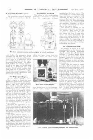
The Control of the Machine.
The power-control gear of the lorry is such that will call for but little attention on the part of the driver. It comprises a hand lever for reversing and linking up, a footoperated throttle—the controlling lever of which is fitted in place or the ordinary clutch pedal, a small hand lever for varying the feed of the donkey pump and coke-firer, and provision for controlling the .drauirlit. There is also a lever provide-1 for rocking the fire bars when leaning out the grate. It is found that one filling of the coke bunker and water tanks is sufficient to run the machine 60 miles ; there is also room provided
for the carrying of an additional supply of coke sufficient for a further 60 miles.
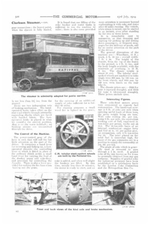
For starting purposes a small wood fire is lighted in the grate, coke is added, and when well alight the bunkers are filled. By this time, usually less than 20 minutes, the motor is ready to start, and no more attention is necessary beyond replenishing it with coke and water after GO miles running. The vehicle, when steam is raised, can be started in an instant, even, after standing by for two or three hours.
It is remarkably easy to manoeuvre, so that stopping and starting for picking up and setting down passengers, or frequent stoppages for the delivery of goods, call for no undue attention on the part of the driver.
The general dimensions of the machine are :—Wheelbase, 14 ft. track, 5 ft. 10 ins. ; overall width', 7 ft. 1 in. The height of the chassis, from the top of the frame to the ground, is 2 ft, 8 ins., and the body length available, with the minimum of overhang, is 12 ft. 6 ins. The chassis 'weight is
about 51 cwt. The tubular steelspoked wheels are machined to take single tires 900 mm. by 120 rum on the front wheels, and 1050 inui. by 120 min. twin bands on the rear wheels.
The chassis prices are :—,t620 for type 5 (upward draught), and i;630 for type 6 (downward draught). These prices exclude tires.
Interesting Figures.
These coke-fired motors prove very economical as regards fuel consumption. The hard-road average is 6 lb. of coke per mile when carrying useful loads of three tons, the gross weight being six tons. With coke costing 16s. per ton, using 6 lb. per mile, the equivalent working cost of fuel, expressed in ton-miles per penny, works out at 11.6. The e0-ton-mile basis of an internal combustion engine lorry and fuel at Is. 4d. per gallon give, . on comparison, only 3.76 ton-miles for Id. The price placed on the solid fuel is somewhat high, for many of the gas companies are in a position to supply the commodity at 14s, 6d, per ton.
The grade of coke which is generally used is screened to pass through a in. mesh. A graded coke of the size known as No. 2 eau be generally obtained from any gas company. Supplies of graded coke for industrial purposes have been established on a satisfactory basis by the London Coke Committee and the Metropolitan Gas Co.