 1
1 2
2 3
3 4
4 5
5 6
6 7
7 8
8 9
9 10
10 11
11 12
12 13
13 14
14 15
15 16
16 17
17 18
18 19
19 20
20 21
21 22
22 23
23 24
24 25
25 26
26 27
27 28
28 29
29 30
30 31
31 32
32 33
33 34
34 35
35 36
36 37
37 38
38 39
39 40
40 41
41 42
42 43
43 44
44 45
45 46
46 47
47 48
48 49
49 50
50 51
51 52
52 53
53 54
54 55
55 56
56 57
57 58
58 59
59 60
60 61
61 62
62 63
63 64
64 65
65 66
66 67
67 68
68 69
69 70
70 71
71 72
72 73
73 74
74 75
75 76
76 77
77 78
78 79
79 80
80 81
81 82
82 83
83 84
84 85
85 86
86 87
87 88
88 89
89 90
90 91
91 92
92 93
93 94
94 95
95 96
96 97
97 98
98 99
99 100
100 101
101 102
102 103
103 104
104 105
105 106
106 107
107 108
108 109
109 110
110 111
111 112
112 113
113 114
114 115
115 116
116 117
117 118
118 119
119 120
120 121
121 122
122 123
123 124
124 125
125 126
126 127
127 128
128 129
129 130
130 131
131 132
132 133
133 134
134 135
135 136
136 137
137 138
138 139
139 140
140 141
141 142
142 143
143 144
144 145
145 146
146 147
147 148
148 149
149 150
150 151
151 152
152 153
153 154
154 155
155 156
156 157
157 158
158 159
159 160
160 161
161 162
162 163
163 164
164 165
165 166
166 167
167 168
168 169
169 170
170 171
171 172
172 173
173 174
174 175
175 176
176 177
177 178
178 179
179 180
180 181
181 182
182 183
183 184
184 185
185 186
186 187
187 188
188 189
189 190
190 191
191 192
192 193
193 194
194 195
195 196
196 Non-slip Differential
Page 68
If you've noticed an error in this article please click here to report it so we can fix it.
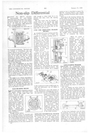
DATENT No. 804,775 describes
improvements for semi locking differential gears that permit slow relative movement between the two road wheels but do not allow one of them to skid freely. (V. Gleasman, 3808 Kirkwood Road, Cleveland. Ohio, U.S.A.) The drawing shows the navel part of
the proposed mechanism. The shaft ends are formed as wormwheels and each meshes with its own worm (1 and 2). The two worms are geared together by spur teeth (3) at bath ends and the whole assembly is carried round by a normal crownwheel attached to the flange (4). For a light drive, a single pair of worms will suffice, but heavier vehicles may have two or even three sets.
The action is dependent on the helix angle of the worms; this determines the degree of reversibility of the drive. When the correct angle is used, the worms can provide the differential action if both wheels are turning, but one worm would lock by friction if complete slip occurred on one of the wheels. The angle for this requirement is 33 degrees from the worm axis.
The angle is very critical, depending as it does on the friction of the thrust bearings and the state of lubrication. For example, if the angle is increased to 36 degrees, it is claimed that free spin can occur if one axle shaft should break, but not if one -wheel is on ice.
BALL-BEARING SPLINE
1VANY independent suspension systems employ splined drive-shaft joints which have to slide under load, and friction created by this
movement may be sufficient to nullify the action of the springs used as resilient members. An improved type of spline in which balls or rollers are interposed between the shaft and its sleeve is shown in patent No. 804,637. (Daimler-Benz A.G., Stuttgart-Untertiirkheim, Germany.) Though normal splines (1) are provided, these are intended only for use during assembly and dismantling. The actual sliding movement is performed by an intermediate sleeve (2) having three or more keys formed upon it. Corresponding keyways in the outer member are
804,637
wide enough to allow balls (3) to be inserted and these form the bearing members.
The ball tracks may be formed as closed loops (4) to prevent the balls escaping as the joint slides. The balls are loaded only on the side that is driven, leaving them free to return idly on the slack side of the keyway.
UNIT FOR OPERATING TRAILER BRAKES
A COMPLETE power-braking unit that I-Ican be mounted on a trailer and coupled to its normal braking system is shown in patent No. 797,801, It is intended for hauliers who, having several trailers, may wish to apply power braking to one of them when an exceptional load has to be carried. (P. Hands, 22 Attwood Avenue, Kew Gardens, Surrey.)
The unit can be mounted on the trailer itself or on the towing dolly of a semi-trailer; the latter is shown in the drawing. The assembly comprises an air-compressor (I) driven by an electric motor powered from the battery of the prime-mover. This charges air reservoirs (2 and 3), one of which is a reserve. The pneumatic servo cylinder (4) is coupled to the mechanical brakes of the trailer by rods and bell-cranks, one of which is shown at 5.
The specification gives full details of all the components, including the electric ally operated valve for controlling the air supply in accordance with the position of the brake pedal. Safety features are incorporated, such as break-away operation and warning lamps to indicate the state of pressure in the reservoirs. Other details are covered by an additional patent numbered 797,802. The first also describes the design of the trailer drawbar.
LEYLAND CENTRIFUGAL CLUTCH rENTR1FUGAL. clutches should not
engage the drive at idling speed, neither should they apply unnecessarily high gripping forces when running at high speeds. A clutch designed with these points in view is described in patent No. 804,759. (Leyland Motors, Ltd., Suffolk House, Laurence Pountney Hill, London, E.C.4.) Referring to the drawing, between the presser plate (1) and the cover plate (2) is a pivot-carrying plate (3); this is urged towards the presser plate by pre-stressed springs (4) abutting on the cover. The driven plate, preferably resiliently mounted (as shown at 5), is carried by the output shaft in the usual way.
The engaging force is applied by bobweights (6) mounted on three-armed levers; at speed the outward movement of the weights causes adjustable pressure pads (7) to compress the friction members.
When the engine is
stationary, t h e prestressed springs prevent
engagement. At idling speeds, the centrifugal movement is initially absorbed by unstressed springs (8), but as the speed rises, these are compressed until they overcome the pre-stressed springs, after which engagement commences. The creation of excessive force due to very high • speed is prevented by abutments (9) which limit the movement of the bobweights.
LOW-LOADING TRAILER
TRAILERS for transporting heavy machinery and similar loads are dealt with in patent No. 805,043. The scheme described enables the road wheels of such a trailer to be retracted to allow the platform to be lowered to ground-level. (L. Hamblin and Sentinel (Shrewsbury). Ltd., Whitchurch Road, Shrewsbury.)
Referring to the drawing, a loadcarrying platform has its rear wheels mounted on trailing arms (1) and its front wheels (which are steerable) carried on a swan-neck structure (2). The enclosing yoke (3) forms the means of attachment to the tractor.
The rear wheels can pivot about the pins (4) and enable the platform to be raised or lowered., by hydraulic rams (5). Normally, the rear wheels lie inside the vehicle width, but once they are lifted from the ground, they can be swung about vertical axes until they 1ie at rightangles to the platform, leaving the rear ramp completely unobstructed.
At the front, hydraulic rams (6) lower the platform, but in this case the wheels remain in their normal plane. The patent suggests that the hydraulic mechanism could also be used to raise or lower the platform to go under obstacles such as low bridges or to increase the clearance for negotiating undulating ground.