 1
1 2
2 3
3 4
4 5
5 6
6 7
7 8
8 9
9 10
10 11
11 12
12 13
13 14
14 15
15 16
16 17
17 18
18 19
19 20
20 21
21 22
22 23
23 24
24 25
25 26
26 27
27 28
28 29
29 30
30 31
31 32
32 33
33 34
34 35
35 36
36 37
37 38
38 39
39 40
40 41
41 42
42 43
43 44
44 45
45 46
46 47
47 48
48 49
49 50
50 51
51 52
52 53
53 54
54 55
55 56
56 57
57 58
58 59
59 60
60 61
61 62
62 63
63 64
64 65
65 66
66 67
67 68
68 69
69 70
70 71
71 72
72 73
73 74
74 75
75 76
76 77
77 78
78 79
79 80
80 81
81 82
82 83
83 84
84 85
85 86
86 87
87 88
88 89
89 90
90 91
91 92
92 93
93 94
94 95
95 96
96 97
97 98
98 99
99 100
100 101
101 102
102 103
103 104
104 105
105 106
106 107
107 108
108 109
109 110
110 111
111 112
112 113
113 114
114 115
115 116
116 117
117 118
118 119
119 120
120 121
121 122
122 123
123 124
124 125
125 126
126 127
127 128
128 129
129 130
130 131
131 132
132 133
133 134
134 135
135 136
136 137
137 138
138 139
139 140
140 141
141 142
142 143
143 144
144 145
145 146
146 147
147 148
148 149
149 150
150 151
151 152
152 A Built-up Crankshaft
Page 52
If you've noticed an error in this article please click here to report it so we can fix it.
PATENT No. 683,085, which deals with a new method of fabricating crankshafts, comes from Isthmian Metals Incorporated, Boston, Massa
chusetts, U.S.A. In this scheme the journals and webs arc made separately in steel and are united by powderedmetal joining plates.
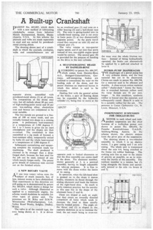
The drawing shows part of a crankshaft in which the journals, crankpins, webs and counterbalances are all separate pieces, pieces, assembled with powdered-metal shims (1) at all joints. The composition of the shims may vary, but all include about 80 per cent. of high-melting-point metal and 20 per cent. low-melting alloy; electrolytic iron and bronze are considered to be most suitable.
The two metals are ground to a fineness of 100 or more mesh, and are initially formed into shape in a coining press. A preliminary heat-treatment at a temperature of 1,500 degrees F. for I to 3 hours is given (in an inert atmosphere) and the shapes arc then re-coined. The crankshaft is then assembled in a jig made of Inconel, a heat-resistant alloy, temporarily united by bolts (2) and the whole heat-treated at a temperature of 1,900 degrees F.
Subsequent normalizing and tempering complete the treatment ready for machining. The shaft produced is claimed to be stronger than a dropforged shaft, because the best steel for the job can be used, instead of one which merely forges easily. The patent gives details of numerous tests carried out on the finished article.
A NEW ROTARY VALVE
AT one time rotary valves were the subject of much research, but, of late, interest seems to have diminished. That experiments in this direction are still going on is demonstrated by patent No. 683,814, which shows a design for such a valve. Although illustrated as applied to a motorcycle engine, the scheme would doubtless be suitable for other types of power unit. The patentees are M. Riley and D.M.W. Motorcycles (Wolverhampton), Ltd., Valley Road Works, Sedgley, Dudley, .Worcs.
The valve is of the conical type, the cone being shown at 1. It is driven A42 by an overhead gear (2) and runs on a roller bearing (3) and a ball-thrust race (4). The cone is spring-loaded into its cylinder-head seating, and is cut away to form ports (5) at two diametrically opposite points. As the ports travel round they uncover an inlet (6) and an exhaust port (7).
The valve rotates at one-quarter engine speed, and if cut into four ports instead of two, one-eighth engine speed would be correct. The second gear (8) is provided for the purpose of handing on the drive to the next cylinder.
A SELF-ENERGIZING BRAKE BY DAIMLER-BENZ
A CCORDING to patent No. 684,297, ri which comes from Daimler-Benz A.G., Stuttgart-Untertiirkheim, Germany, self-energizing brakes are inclined to concentrate the wear on the leading ends of the shoes, and the patent discloses an improved layout. in which this defect is said to be overcome.
Dealing first with the general action of the brake, a pair of floating shoes can be expanded by the hydraulic cylinder (1), being free to move at the opposite ends in forked abutments so that the shoe assembly can centre itself in the drum. The abutment member, shown generally at 2, is a screwed assembly, having its length adjustable for take-up purposes. It is free to move with the shoes within the limits of its easing.
In operation, when the left-hand shoe is pressed on to the drum it moves bodily, transmits its thrust through the sliding abutment and loads the bottom of the right-hand shoe. So much is fairly common practice, but the novelty in this case lies in the shape of the abutment faces (3 and 4).
These are sloped at such an angle that they create an inwardly directed component of force which tends to decrease the load at these usually .heavily loaded points. The angle on the thrust end (5) is sloped in the opposite dir&tion so as to increase the load, the net result being to even-out PETROL-PUMP DIAPHRAGMS
THE diaphragm of a petrol pump has very arduous duties, and the best material has yet to be discovered. Claims are made in patent No. 684,598, for a material said to be efficient and durable. A close-woven cotton material called " chafer-duck " forms the basis; this is stretched between rollers until the warp threads are 10 per cent.
longer. in this condition, synthetic rubber is forced into the material, and subsequently cured. Buna-N is said to be a suitable rubber for the job. The patentee is Carter Carburetter Co., St. Louis, Missouri, U.S.A.
INDEPENDENT SUSPENSION FOR TROLLEYBUSES
AMOTOR to each wheel and independent suspension are the chief features of a trolleybus power unit shown in patent No. 684,454, by Porsche Konstruktionen G.m.b.H., Salzburg-Morzg, Austria. In the scheme shown, the electric motors form the pivot pins of the suspension.
The drawing shows a two-wheeled assembly in which 1 is an electric motor, 2 a gear casing and 3 an axle casing. The whole unit is trunnioned about the axis 4-4, being attached to the frame via rubber bushings. The rocking axis lies as near to the centre of gravity as possible, so as to minimize the inertia of the assembly. The resilient member is a torsion bar (5) lying alongside the frame and universally jointed to the axle via levers (6 and 7).