


Flame Heater to Facilitate Oil-engine Starting
Page 40
If you've noticed an error in this article please click here to report it so we can fix it.
DATENT No. 541,400 comes from a
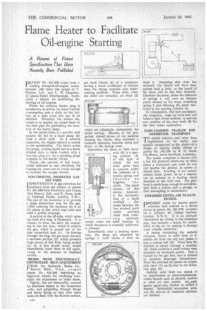
leading transport-oil-engine manufacturer, afid bears the names of F. Perkins, Ltd., and C. W. Chapman, 17, Queen Street, Peterborough. It discloses a scheme for facilitating the starting of oil engines.
Whilst the ordinary heater plug is satisfactory in action, its heavy current consumption puts a drain on the battery at a time when this can ill be afforded. Therefore, the scheme disclosed is to employ an actual flame in the inlet pipe for performing the function of the heater plugs.
In the intake there is a paraffin mist sprayer (2) fed by a hand pump (3) from a small tank. As a suitable apparatus, the Kigass injector is named in the specification. The driver works the pump, causing liquid fuel in a finely divided state to make contact with a hot-wire plug (1) (or a sparking plug) included in the starter circuit.
Clearly the amount of fuel burnt, whilst sufficient to heat effectively the in going air, must not be nearly enough to exhaust the oxygen therein.
NON-CHOKING PRODUCER GAS OFF-TAKE
IMPROVEMENTS in gas-collectors for lproducers form the subject of patent No. 541,080 from Parkinson and Cowan (Gas Meters), Ltd., and K. Green, both of Terminal House, London, S.W.1. The aim of the invention is to provide a large abstraction area for the gas, whilst reducing the tendency for it to lift pieces of fuel which may cake and form a partial stoppage.
A section of the oil-take, which takes tiie form of a ring, is illustrated. It is annular in form, the skirt (3) extending to the fire zone, where it collects the gas, which is passed out of the pipe connection boss (1). In flowing through the ring, the gas must traverse a narrower portion (2), which prevents large pieces of fuel from being sucked up, or, if this should occur, would immediately cause them to fall again, owing to the absence of localized suction.
BRAKE WITH FRICTIONALLY CONTROLLED SELF-ADJUSTMENT CROM the Hydraulic Brake Co., Detroit, Mich., U.S.A., comes patent No. 541,095 describing an improved scheme for rendering automatic the adjustment of brake shoes.
Tightly, but not immovably, secured by frictional means to the brake-shoe webs, and projecting through flange and fabric facing so that their outer faces are flush with the friction surface, are hard blocks (5) of a substance having a lower co-efficient of friction than the facing material and better wearing qualities. These abut, when the shoes are retracted, on stops (2)
which are adjustable, presumably, forinitial setting. Because of the properties, named above, of the material forming the blocks, they maintain a constant clearance between shoes and drum, as the facings wear.
Separating the shoes at their lower
544 3 70 ends (6) is a spacing 'cylinder (4) of the type in which the two main parts tend to unscrew, under the influence of a torsion spring, and thereby to
lengthen t h e whole. The novel feature of this device, however, is the incorporation of a small multiple disc brake between the two screwed parts which prevents them from rotat i n g relatively except when the axial loading, to which the spacer is normally subjected, is released.
Immediately after a braking operation, the shoes are retracted by springs I, until blocks 5 abut on
stops 2. Assuming that' wear has occurred, the blocks will have been pushed back a little, so the travel of the shoes will be less than formerly. Therefore the shoes, under the influence of springs 1, will rock on fulcrum points formed by the stops, stretching .spring 3 and releasing the small discbrake in the spacing cylinder (4).
In consequence, this unit automatically lengthens, tak-es up back-lash and forms a rigid thrust member, to suit the new position of the shoe heels (6) for the next brake application.
EASY-LOADING TRAILER FOR AGRIMOTOR TRANSPORT enable tractors and other farm 1implements to be easily and -quickly transported is the object of a design of tipping trailer shown in patent No. 541,205 by R. H. Good, The Manor, Aston Sandford, Aylesbury. The trailer comprises a chassis with a low flat platform which can be tilted about a horizontal axis until its rear end reaches the ground, as shown in dotted lines. Loading, if not accomplished under power, as by a tractor, can be assisted by a hauling winch mounted at the front end. The platform is made large enough to accommodate both a tractor and a plough, so that uncoupling is unnecessary.
ENRICHED EXTRA AIR TO SAVE PETROL
PRESENT needs for drastic petrol economy lend interest to a device shown in patent No. 541,370, invented by. A. Jackson, 46, Temple Gardens, London, N.1N.11. It is an extra-air attachment for fitting to the induction pipe, but includes a means for enrichment of the air by passing it through some volatile substance.
A casing containing the suitable chemical, shown in solid form at 5, admits air from the top and passes it into a central bell (4). From here the mixture is drawn through a chamber. (3) which contains a small rotary vane mounted on hardened points. This is turned by the gas flow, and is claimed to promote thorough intermixture. Then the enriched air passes an adjustable valve (1) on its way to the induction pipe (2).
Suitable solid fuels are stated to be naphthalene or paraformaldehyde, whilst liquids such as alcohol, acetone or ether are also named. An ,,,antiknock agent may 'further be added if desired. Substantial economies, without the defects Of weakened mixture. are claimed.