


HINTS ON MAINTENANCE.
Page 30
If you've noticed an error in this article please click here to report it so we can fix it.
How to Get the Best Out of a Vehicle, to Secure Reliability and to Avoid Trouble.
323.—Improved. Method of Lubricafing Frent End of Torque Tube on F.2 Type Fiat.
As a result of the excessive noise and vibration occurring in the transmission of an F.2-type Fiat chassis, the rear axle was removed and completely dismantled. It was then found that the front bearing of the propeller shaft, which is enclosed in the torque tube, had received no oil for some time and was, consequently, badly worn also the yoke at the
front end of the torque tube, which should have been free in the latter to allow for uneven deflection of the rear springs, had become a fixture due to rust.
It is intended by the designers that these parts should be lubricated by oil creeping up the propeller shaft from the differential casing, hut, in this ease, although there was an ample supply of oil in the axle, it had failed to reach these two important points. It was, therefore, decided to provide a positive oil supply to them from another source Grease or oil cups presented themselves as the most simple remedy, but these are apt to be overlooked so were not fitted.
Now, in this vehicle the two yoke support pins at the back of the gearbox are lubricated by. oil under pressure supplied by an oil pump on the engine, the driver periodically depressing a valve on the dash for this purpose. The problem was to make use of a part of this supply for lubricating the aforementioned points.
The worn white-metal bearing for the propeller shaft was discarded and a ball race. 72 mm. by 35 mm. by 23 mm. was substituted, and this was found to fit exactly without any alteration except the provision of a distance piece at the front.
In one eye of the yoke, directly over the oil-hole in the support pin, a hole was drilled and tapped gas thread. Into this was screwed a suitable elbow to take the nipple nut of a piece of +-in. copper pipe. A similar elbow was screwed into the sleeve of the yoke, as shown in the illustration, and was so situated that the oil hole communicated With the recess in the yoke sleeve which, when the torque tube is in position, forms an annular oil reservoir.
The eight small holes in the end of the torque tube
• 1344
were next plugged and a groove was cut along the top of the torque tube terminating in a hole communicating with the interior of the tube in front of the new ball bearAig. The ,oil under pressure is thus delivered to the oil reservoir and thence to the ball race, through which any excess finds its way to the differential casing.
324.—A Cause of Power Loss in the Foden • Engine.
One of the reasons why difficulty is occasionally experienced in maintaining steam and in obtaining the full power from the engine of the Foden wagon lies in the three-way cock which diverts the highpressure exhaust to the 'chimney when working "double high." This cock is kept up to its face by a packed gland, and should the packing be -at all loose, the cock tends to fall away from its seating, thereby permitting a portion of the exhaust from the highpressure cylinder to escape to the atmosphere, so causing a loss of power in the low-pressure side. The glands should, therefore, be kept packed just tight enough to allow the lever to be pulled over with a slight effort. Care should also be taken that the faces of the cock and the seating are good.
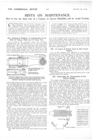
325.—Improving the Suspension of the Vulcan Engine.
The engine employed on the Vulcan 30-cwt. and 2ton vehicles is three-point suspended in the chassis. The front end rests in a leather bush, whilst the two rear arms of the crankcase, which is of aluminium, rest on two angle brackets attached to the 4rame. These two arms are held in their brackets by steel bolts, and in course of time these.bolts sometimes work slack, and unless the play be taken up immediately the power unit bounces up and down at its rear end and hammers down the lower face of each crankcase arm. This allows the engine to drop slightly and thus become out of alignment with the gearbox, and if the trouble is of long duration it causes jamming of the clutch withdrawal gear.
One way to cure the trouble it to build up the faces by welding. Another method is to fit over the
faces two square pieces of -in. sheet steel, riveted in position as shown in the illustrations.