


AN EXTENSION OF THE COMMER CAR RANGE.
Page 11
Page 12
If you've noticed an error in this article please click here to report it so we can fix it.
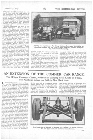
The 3P-type Passenger Chassis, Modified for Carrying Gross Loads of 4 Tons. The Additions Include an Entirely. New Back Axle.'
USERS and potential users of Commer_Car vehicles will he interested tolearn of an addition to the range of chassis now Marketed. This takes the form of a modificatibn of the 3P type chassis designed exclusively for the carrying of• goods; actually, it will bear a net load of 4 tons with a platform body or 3 tons with a van body. The production of the 3P type is, of course, being continued, and the new chassis will he known as the 3G type.'
The general design ofthis vehicle resembles that of its prototype so, far as the engine and gearbox are concerned. The main differences lie in thepropeller shaft and back axle. In the SP typo there is a short propeller shaft leading to a second shaft enclosed in a tubular torque member, but in the 3G type there is a ,single propeller shaft with star type universal joints and an overhead wormdriven axle which embodies many interesting and practical points in its design. We will now give a brief general description of the chass-is and then refer in detail to any particularly interesting points. The engine has•four cylinders cast in pairs, and with a bore and stroke of 115 mm. and 140 mm. respectively, developing 40 b.h.p. This' power unit is supported at its front end in a parallel steel bush carried in the front cross-member, thus the starting handle is always in alignment.
At the rear end is a cast-steel engine bearer, which forms a housing for the rear ball bearing of the ciankshat,.whilat its ends are carried by the frame side members.
Following Commer Car practice the tappets are carried in an extension of each pair of cylinders, so that the whole
base of each pair can be machined, male ing an oiltight casing when the cover plate is fitted. The induction passage for the carburetter is formed in the cylinders below the water jackets. The drive from the engine is taken through a leather-faced. cone clutch with a light, pressed-steel body engtiging with a, steel flywheel. Behind the clutch is a single Hardy disc joint. The patent gearbox, which is threepoint suspended from two cross-members, gives four speeds forward and a reverse, all the gear changes being effected by the engagement of dog clutches.
Behind the gearbox is a loco type foot brake, and thence the drive to the back axle is as already described.
The frame is of pressed steel channel 71-in. by 21-in. section at its deepest point, tapered to front and rear and inswept slightly at the front end. The radiator, through which tho water . is circulated on the tbermo-siphonic principle, is supported on trunnions, end • held at the top by a stay from the upper water pipe of the cylinders.
De'aling with details, there are several very interesting points about the engine. For instance, the lubricating oil is circulated by a Retoplunge pump and passes through a visible flow indicator on the dash.
Oil from the first big-end scoop is thrown to a special collector and led to the timing case, the correct level in -this being assured by a hole between it end the crankcase. This and the hole above it also allow the insertion of rods which facilitate the removal of one of the bearings in the crankcase. The oil is carried to each big-end trough through a brass tube cast into the crankcase.
The clutch spigot is spherically ended, and by removing the intermediate piece between this spigot and the spider of the universal joint, the clutch can be dismantled and lowered with the spigot un til it can be freed without removing ui)., other part. The clutch centre itself is permitted to do this by the use of a Skefko bearing.
The patent gearbox was described by us some time ago, but we may point out that the reverse spindle is carried right across the box above the ordinary gears and its bearings are housed in the main walls. When the first and second gears are in mesh they are close up to their bearings, and thus the load is not imposed in the middle of the countershaft.
A simple but effective type of selfsealing gland is employed for the gearbox.
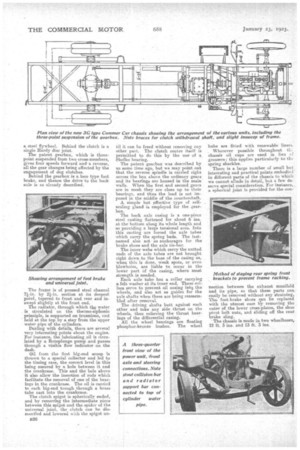
The back axle casing is a one-piece steel casting flattened for about 6. ins. at the bottom along its whole length and so providing a large tensional area. Into this casting are foroed the axle tubes which carry the spring beds. The lastnamed also act as anchorages for the brake shoes and the axle tie-bar.
The inner Webs which carry the nutted ends of the axle tubes are not brought right down to the base of the casing as, when this is done, weak spots, or even blewholes, are liable to occur in the lower part of the casing, where most strength is needed.
Each axle tube has a collar carrying; a felt washer at its inner end. These collars serve to prevent oil oozing inky the wheels' and also act as guides for the axle shafts when these are being reassembled after removal.
The driving shafts butt against each other and take any side thrust on the wheels, thus relieving the thrust bearings of the differential casing.
All the wheel bearings are floating phosphor-bronze bushes. The wheel hubs are fitted with renewable liners Wherever possible throughout 111 chassis oil cups are used in lieu ef greasers; this applies particularly to the spring shackles. There is a large number of small but interesting and practical points embodied in different parts of the chassis to which we cannot allude in detail, but a few de. serve special consideration. For instance, a spherical joint is provided for the con motion between the exhaust manifold and its pipe, so that these parts can easily be removed without any straining. The foot-brake shoes can be replaced with the utmost ease by removing the outer of the lower cross-plates, the shoe pivot bolt nuts, and sliding off the rear brake sling. The chassis is made in two wheelhaaes, 12 ft. 3 ins. and 13 ft. 3 ins.