


PATENTS SUMMARIZED.
Page 22
If you've noticed an error in this article please click here to report it so we can fix it.
Producer-gas Plants.
In our issue of the 29th August last we described at some length a suctiongas plant suitable for carrying on a motor vehicle chassis and for generating gas for use in the engine of that chassis. The patentee was J. W. Parker, of 32,
Radnor Road, Harrow, and ho has evidently been experimenting with the•apparatus then described, since the specification No. .121;166 embodies certain improvements upon it, and we take it that these are the result of practical experience with the mechanism which we have already described. The gas generator or producer is normally carried at the back of the vehicle, and pipes convey the gas therefrom to the induction pipe of the engine. The necessary water is supplied by means of a small engine driven pump, taking its supply from a tank below the chassis, and delivering it below the firebars of the producer. The present invention covers a means of forcing air into the generator rather than leaving it. for the suction efieat of the engine. For this purpose a speEial type of blower fan is substituted for the component which is usually behind the radiator of a car, and it, is driven in the. same manner. The air, which, it should be noted, is conveniently warmed by pas,sage through the radiator, is delivered by the fan into a sort of cowl, and driven thence along a p'pe to the generator. The latter, it will be remembered, was so constructed that the entering air had to pass through a jacket, and this has the double effect of heating the air preparatory V/ its passing through the fire, ar-d
at the same time cooling the exterior of the generator. • The pipe from the fan delivers into this jacket space. A similar pipe withdraws the gas from the generator, and delivers it, as we have said, into the induction manifold of the engine. A further improvement takes the form 048 of pressure-supplied air to the engine. A branch pipe from that which couples the fan chamber to the generator leads as a by-pass into the pipe from the generator to the engine. There is a valve in this branch so that the amount of air passing can 'be regulated. In this way is the combustible mixture formed.
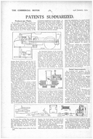
An important feature of the inventioa relates to the method for driving the fau when the engine is stationary. We will consider first the method which is illustrated on the drawing which we repro
duce. The fan pulley is loose on its spindle, and is provided on that side further from the fan itself with clutch dogs. A sliding bevel gear-wheel keyed to the fan spindle is also provided on one side with dogs which can be made to engage with those on the fan pulley. A bevel wheel which may suitably be engaged with that on the eliding member is keyed to the transverse shaft which emerges from the bonnet, and to the end of which may be fixed a handle. For starting the generator the two bevels are engaged, and the fan rotated by the hand gear. So Soon as the fire is going and gas being generated, and after the preliminary fuel products of combnst'on are got rid of by temporarily opening the to of the fuel hopper, the bevel gears are slid oul of engagement, and the fan pulley coupled to the spindle and fan. The engine may then be started, and the operation proceeds thereafter automatically.
Alternative methoda-of driving the fan while the engine is stationary and eliminating the need for hand control in
elude the substitution of a small electric motor, the current from which may be derived from storage batteries which 'have been charged in the usual way by tho engine acting through a lighting dynamo. As an alternative to the slid, ing gears and dogs a ,free_ wheel device may be used so that whichever method of driving the fan is turning at the highest speed actually transmits the drive. An important claust in the inmention is one which suggests the enrich; /tient of the mixture by the' addition of some hydro-carbon, such additional hydro-carbon being preferably supplied to the gas by passing the latter' over•the jet of any carburetter suited for use on road vehicles operated by petrol ov paraffin.
Prodacer-gas plants for automobiles are attracting a good deal of attention just now. In addition to the above important contribution there is another, No. 121,161, by H.W. }limber, although this relates merely to a slight detail modification in connection with tho water supply to the generator. A bypass valve is inserted in the passage for the water from pump of tank to producer, and this by-pass valve is controlled by the erig-ne throttle, So that with the engine stopped, all the water which would be supplied to the producer is by-passed, but with the engine running at greater and greater speeds, less and less water is by-passed and more
passed direct to the producer. ,
Detail Improvements.
Corbella and another, in No. 112,452, describe a method of operating the two valves of an iaternal-combustion engine, using only one cam.
W. H. Smith describes in No. 120,959 an arrangement of piston rings. Two rings of L-section, which together form a channel, are sprung outwardly against the cylinder walls by an inner plain spring: The contact between spring and rings is such that the two halves of the ring are forced outwards against the groove of the piston as well as against the walls a the cylinder.
No. 120,966, by C. W. Stamper, is a Vpping device for wagons: In unloading the wagon body is pulled to the rear and automatically tips, due to its weight and that of the load, independently of the position of the latter in the body.
A means of storing coal-gas on board a motor vehicle is the subject of No. 120,967, by A. R. Moody. A containci of any convenient shape with quick de tachable cover carries a tray full of char
coal, which iS intended to absorb the gas.
An ingenious speed control for petrol electric transmission is the subject of Nod 120,987, by J. Cartier. The worm shaft of a worm-driven axle is coupled directly to the armature spindle, and is allowed a certain endwise motion, being partially controlled by means, of a spring.