


Patents Completed.
Page 18
If you've noticed an error in this article please click here to report it so we can fix it.
LUBRICATING SYSTEM.—IIesketh and Another.—No. 6,523, dated 18th March, 1907.—The crank shaft (A) is sur
rounded by a floating bearing (B), the interior of which is formed with a circumferential groove (b), the latter being in communication with a conduit (C) connected with a force pump (E). The circumferential groove (b) communicates with a channel (a2) in the crank shaft (A) by means of an orifice (a). The channel (a2) communicates with a passage (a3) which extends through the centre of the crank shaft (as at a4), and has openings (a5) at earls of the bearings. It will he seen that, at each ievolution of the crank shaft, oil will be forced through the channels (a2, a3) to each of the bearings.
COOLING APPARATUS. — Daimler Motoren Gesellschaft.—No. 19,269, dated (under Convention) 5th December, 1906. —The water cooled in the radiator (al passes through the conduit (b) in a jacket surrounding the change-speed gearing box (c) ; from thence it passes through the conduit (i) into a jacket surrounding the lower part (k) of the engine casing. The water flows from the lower casing (Ie) through the conduit (1) into the upper casing (m), and it is then drawn off by the circulating pump (a) and forced through the conduits (t, a) into the cooling jackets of the cylinders (r, gl. From these cooling jackets the water returns to the radiator (a) through a conduit (.5). It will be seen that this system not only cools the cylinders but also the working parts which become heated by friction,
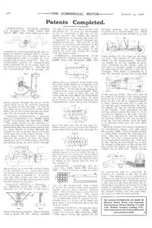
NON-SLIP DEVICE. — Whitaker. — No. 26,623,06, dated 10th April, 1907.— Brackets (F) are secured to the chassis behind the driving wheels. These brackets form a guide for the sliding member
(D), the lower end of which carries rubber blocks (R). A lever (L), fulcrummed at B, is connected to the top of the sliding member (D). When the vehicle has a tendency to side-slip, the lever (L) is operated by the. driver through any suitable mechanism. The end (P) of the lever (L) is moved in the direction of the arrow, and the sliding member (D) is forced down against the action of the spring (G) until the blocks (R) engage with the road-surface.
COMBINED DEODORIZER AND SILENCER.—Wakley and Another.—No. 28,647, dated 15th December, 1906.—The
exhaust box, or silencer, is provided with the usual baffle plates (a, a) together with inlet and outlet pipes (6, c) for the exhaust gases. At the top of the casing (a) a water supply pipe (f) is arranged. This latter has a series of saw cuts on its under side through which the water flows into the casing (a). A series of wire gauze screens (ra) divide the casing (a) into compartments, there being one compart
ment for each saw cut in the pipe (/). These screens serve to prevent the exhaust gases from blowing the water through the
casing (a). The water, having purified the exhaust gases in its flow from the top to the bottom of the casing (a), flows into a filter (la) which collects the pungent matter, and oil, and allows the filtered water to return to the supply tank by way of the conduit (i).
RADIATOR. — Larnplaugh and An()then—No. 2,01.8, dated 26th January, 1907. — This invention relates to radix tors of the honeycomb type, formed of series 'of circular tubes and approximately square tubes having concave sides. The circular tubes (a) are formed
with expanded ends (a?). The square tubes (b) are arranged between the tubes (a), so that their ends fit against the expanded ends (a1) of the round tubes, and thus leave a space between them for the flow of water.
MOTOR VEHICLE.—Societe des Automobiles Traffault.—No. 6,514, dated (under Convention) 28th February, 1907. —The engine drives the pulleys (S, Si)
through gearing, the pulleys being mounted on a counter-shaft (y). These pulleys drive by means of belts (t, 11) two
larger pulleys (T, Ti), fixed on the drivi tg axle. The pulleys (T, Ti) drive the wheels (A, Al) independently. The driving wheels (A, Al) are capable of movement, relatively to the chassis, and, in this way, a variable speed is obtained. At each side of the chassis a rod (p) is arranged. This latter is enclosed by a tube (0) secured, at one end, to the hub
of the driving wheel. The other end of this tube is connected to the change speed lever (L) by a rod (M). On actuating the lever (L) the rod (M) is displaced which, in turn, causes the tube (0) to slide on the rod (p), and, consequently, the driving wheels (A, Al) are moved relatively to the chassis. This movement of the driving wheels causes the belts (t, el) to slacken, or tighten, as the case may be. When it is required to free the engine, the driving wheels (A, Al) are moved toward the steering wheels until the belts (t, tl) become loose and slip over their pulleys.
MOTOR VEHICLES FOR CARRIAC;E OF AN1MALS.—Davis.—No. 540, dated 8th January, 1907.—This invention relates tn motor road vehicles for carrying animals. The rear of the vehicle bOdy is divided into two compartments (B, C) by a longitudinal partition (A). The back of the vehicle is constituted by a door (K) hinged to the floor of the vehicle and kept closed by means of springs (L) arranged one on each side. These springs
are carried by rods (1) supported by brackets (12) secured to the side of the body. The spring (L) is in compression between one end (12) of the rod (1), and a connecting member (M); it thereby assists the return of the door (RI from the inclined plane (as shown in Figure 1) to the closed, or upright, position. The door is provided with side railings (N) to prevent the animals falling over the edge when the door is in the inclined position.