


An Engine With "Part-time" Cylinders
Page 58
If you've noticed an error in this article please click here to report it so we can fix it.
mOVEL proposals in engine design are made in patent No. 649,292, which comes from the Bendix Aviation Corporation, South Bend, Indiana, U.S.A. The principal feature of the engine is a means for rapidly switching some of the cylinders in or out of action as the demand for power varies.
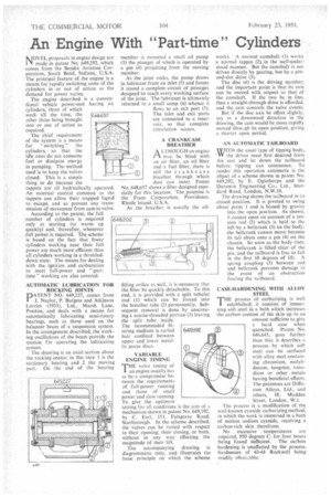
The engine described is a conventional vehicle power-unit having six • cylinders, three of which work all the time, the other three being brought into or out of action as required.
The chief requirement of the system is a means for " switching " the cylinders, so that the idle ones do not consume fuel or dissipate energy in pumping. The method used is to keep the valves closed. This is a simple thing to do because the tappets are all hydraulically operated. An external control common to the tappets can allow their trapped liquid to escape, and so prevent any transmission of movement from cam to valve.
According to the patent, the full number of cylinders is required only at starting (to warm up quickly) and, thereafter, whenever .full poWer is required. The scheme • is based on the fact that fewer cylinders working near their full power are much more efficient than all cylinders working in a throttleddown state. The means for dealing with the ignition and carburation to meet full-power and "parttime" working are also covered. 648.657 AUTOMATIC LUBRICATION FOR ROCKING JOINTS
PATENT NO. 649,227, comes from J. Naylor, P. Burgess and Atkinson Lorries (1933), Ltd., Marsh Lane. Preston, and deals with a means for automatically lubricating semi-rotary bearings, such as those used on the balancer beam of a suspension system. In the arrangement described, the working oscillations of the beam provide the motion for operating the lubricating system.
The drawing is an axial section about the rocking centre; in this view 1 is the stationary bearing and 2 the moving part. On the end of the bearing
member is mounted a small oil pump (3) the plunger of which is operated by a pin (4) projecting from the moving member.
As the joint rocks, the pump draws in lubricant from an inlet (5) and forces it round a complete circuit of passages designed to reach every-working surface of the joint. The lubricant is ultimately returned to a small sump (6) whence it flows to an exit port (7). The inlet and exit ports are connected to a reservoir, so that complete circulation occurs.
A CRANKCASE BREATHER
A LTHOUGH an engine 1-1 may be fitted with an air filter, an oil filter and a fuel filter, there is still the crankcase breather through which dust can enter. Patent No. 648,657 shows a filter designed especially for this location. The patentee is the Fram Corporation, Providence, Rhode Island, U.S.A.
As the breather is usually the oil
filling orifice as well, it is necessary that the filter be quickly detachable. To this end, it is provided with a split tubular end (1) which can be forced into the breather tube (2) permanently. Subsequent removal is done by unscrewing a coarse-threaded portion (3) leaving the split tube inside. The recommended filtering medium is curled hair confined between upper and lower metallic gauze discs.
VARIABLE ENGINE TIMING E valve timing of an engine usually has to be a compromise between the requirements of full-power running and those of small power and slow running. To give the optimum setting for all conditions is the aim of a mechanism shown in patent No. 649,192, by C. Earl, 151, Falsgrave Road, Scarborough. In the scheme described, the valves can be varied with respect to their opening, their closing, or both, without in any way affecting the magnitude of their lift.
The accompanying drawing is diagrammatic only, and illustrates the basic principle on which the scheme
works. A normal camshaft (1) works a normal tappet (2) in the well-understood manner. But the camshaft is not driven directly by gearing, but by a pinand-slot drive (3).
The disc (4) is the driving member, and the important point is that its axis can be moved with respect to that of the camshaft. If the two be in line, then a straight-through drive is afforded, and the cam controls the valve events.
But if the disc axis be offset slightly', say in a downward direction in the drawing, the cam would be more rapidly moved throu;gh its open position, giving a shorter open period.
AN AUTOMATIC TAILBOARD %WITH the usual type of tipping body. W the driver must first descend from his seat and let down the tailboard before tipping can commence. To render this operation automatic is the object of a scheme shown in patent No. 649,202, by E. Oglethorpe and the Duramin Engineering Co., Ltd., Siandard Road, London, N.W.10.
The drawing shows the tailboard in its .closed position. It is pivoted to swing about point 1 and is biased by gravity into the open position. As shown, it cannot open on account of a tension rod (2) which is held to thc left by a bellerank (3) on the body: the belkrank cannot move because its tail abuts onto a pin (4) on the chassis. So soon as the body rises, the belIcrank is lifted clear of the pin, and the tailboard is free to fall in the first 10 degrees of lift. A spring coupling (5) between rod and beficrank prevents damage in the event of an obstruction fouling the tailboard.
CASE-HARDENING WITH ALLOY STEEL
THE process of carburizing is well established; it consists of immersing soft steel in a bath which increases the carbon content of the skin up to an amount sufficient to give a hard case when quenched. Patent No. 646.645, goes further than this; it describes a process by which soft steel can be surfaced with alloy steel containing chromium, molybdenum, tungsten, vanadium or other metals having beneficial effects. 'Ilse patentees are Diffusion Alloys, Ltd., and others, 18, Maddox
Street, London, W.1. • The process is a modification of the well-known cyanide carburizing method, in which the work is immersed in a bath of molten sodium cyanide, receiving a carbon-rich skin therefrom.
No excessive temperatures are required, 950 degrees C. for four hours being found Sufficient. The carbon hardening is unaffected by the process. bardnesses of 63-64 Rockwell being readily obtai.lable.