


An Induction-heating Hardening Process T HE modern method of induction heating
Page 60
If you've noticed an error in this article please click here to report it so we can fix it.
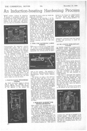
is particularly suitable for hardening gear teeth, because the teeth alone can be heated and quenched, instead of the whole gear, and distortion can thus be practically eliminated.
Unfortunately, the apparatus requires considerable power, and to improve matters in this rtspect is the object of a scheme shown in patent No. 629,464, by Standard Telephones and Cables. Ltd., 63, Aldwych, London, W.C.2.
In the drawing. I is the gear to be worked upon. It is inserted in a travelling carriage (2) which is propelled along the quenching tank (3) by chains, not shown. Overhead is the inductionheating coil (4); this is of wavy outline so as to embrace three sides of each tooth. In operation, as the carriage is pulled along, the gear is rotated by a rack (5) via an idler (6) so that the teeth pass in turn into the heating region and then descend into the quenching fluid with the minimum of delay, Speed of operation is the main factor in the improved economy, betause, as conduction losses are therefore low, the total power input can also be lower.
A SLEEVE-VALVE TWO-STROKE ENGINE
A NEW two-stroke engine is shown in patent No. 629,620, by P. Boudier, Viroflay, France. One novelty of the scheme is the means for
operating the sleeve valve by which the ports are controlled.
Referring to the drawing, ,1 is the sleeve which controls inlet ports (2) flt1 exhaust ports (3) at the appropriate moment. The sleeve is fitted with a bridge-piece containing a curved slot (4). Rollers on the connecting-rod work in this slot and translate the crossmotion of the rod into up-and-down movement of the sleeve. Other features of the patent are the use of a flat exhaust belt (not shown) surrounding the ports, and an annular compression space (5) in which self-ignition is initiated by the rising of the sleevevalve. The crank circle shows a timing diagram in which the thick line, 6, is exhaust opening, and line 7 the inlet period.
A TOOL FOR HANDLING LARGE WHEELS TO work on the tyre of a large wheel is often a serious problem in manhandling, and patent No. 629,449, shows equipment that should prove of assist
ance in this respect. The patentee is the Branick Manufacturing Company, Incorporated, Fargo, North Dakota, U.S.A.
The device can pick a rim and tyre from the floor and lift it to a convenient working level; it can also swivel the wheel about a horizontal axis, so that any part of the tyre can easily be worked upon. In the drawing, the wheel is held by an internally expanding chuck having two fixed jaws (1) and a third one operated by air pressure.
The chuck is mounted on a horizontal pin so that the tyre can be moved to any desired angle by a worm-and-wheel (2) operated by a handwheel (3). The upright member (4) is pivoted at its lower end, and can be rocked to the left by a screw-jack (5), a movement which enables the wheel to be picked up from the floor.
A RESILIENT SUPPORT FOR PROPELLER-SHAFTS
TO support the propeller-shaft of a vehicle, whilst allowing it to move under the influence of road inequalities, is the aim of a scheme shown in patent No. 629,502, by T. Charlesworth, and The Laycock Engineering Co., Ltd., both of Victoria Road, Sheffield, 8.
The drawing shows an end view; the propeller-shaft (1) is journalled in a ball-bearing carried in a housing (2). The housing is fitted with trunnions (3) which rock on needle bearings housed in a forked forging (4). The latter is bolted to the frame via rubber bushes (5) which permit the slight motion required. The bearing members are adequately protected from the ingress of dirt, and provision is made for lubrication.
AN OIL ENGINE WITH ROTARY VALVES
A NOVEL design for .a compressionignition engine employing rotary valves, is shown in patent No. 629,465, by T. Telichowski,• 100, Island Road, Birmingham, 21. This inventor mentions the difficulty encountered in finding room for a fuel injector in the head of a rotary-valve engine, and he overcomes it by placing the injector actually inside the valve.
The drawing shows, partly diagrammatically, a section through the valve assembly. 1 is the rotary valve; this runs in a housing in the cylinder head and contains the usual inlet and exhaust ports. The injector-cum-pump (2) is placed as shown, being operated once per revolution as it passes a stationary cam (3), and returned by -spring pressure.
The cam is adjustable for angular position, being cut with gear teeth to engage an operating pinion (4). This not only adjusts the timing of the charge, but also its quantity, because the cam guide-gitoove (5), being eccentric with the valve. alters the effective distance of the lift.
The fuel has of course, to be taken to the interior of the valve barrel by a
running seal, and this is located in the driving spindle. The inventor claims that a better mixture of fuel and air is obtained by this scheme, on account of the fuel jet sweeping across the combustion space.