


A TOWER WAGO1 R ROAD OR RAIL.
Page 16
Page 17
Page 19
If you've noticed an error in this article please click here to report it so we can fix it.
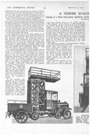
ONE OF the most interesting two-purpose vehicles which we have had the pleasure of examining is the novel tower wagon which has been in use in Liverpool for some weeks and which was designed for use in executing repairs to the overhead equipment of tramway tracks during the ordinary working day.
The Corporation of Liverpool has under its control one of the most progressive tramway undertakings in the country, and it is tackling the problem of suburban transport from quite a new angle, by the developMent ef enclosed tramway tracks along which ears may travel at a speed up to 20 m.p.h. in perfect safety.
At the present time some 12 miles of track hedged off horn the ordinary road are in service, and new schemes which will considerably increase this mileage are being proceeded-IN/1th apace. Now, with tracks laid off the main roads, one of the most difficult problems which presented itself was how to achieve convenient supervision and repair of the overhead equipment. For ordinary service in this direction, the corporation has a fleet of some 10 petrol and electric tower wagons, but these were designed only for road use, and when endeavours were made to utilize them on unmade roads it can readily be imagined what happened—the wheels sank into .soft ground and unameuvring them in such restricted space caused considerable trouble.
As a temporary expedient, a tower wagon running on grooved trackwheels was employed and used as a trailer in conjunction with an electric car, and as much of the work was done at night the tramcar services were not unduly interfered with, but the Tramway's Department wanted a new type of vehicle which would be equally serviceable for executing repairs in the course of the ordinary working day as well as at night. Consequently, the .dual-purpose tower wagon which we describe was evolved by Mr.
P. Priestly, the general manager of the Liverpool Corporation Tramways, and the staff under his control, and we consider that every credit is due to them for evolving such a novel and practicable machine, and one which is giving very satisfactory results.
It was actually constructed at the Lambeth Road car sheds; Liverpool, and the present vehicle, which is of a somewhat experimental nature, was chiefly built up from odd components, the frame, for instance, being a Tilling-Stevens, in which is mounted a 45 h.p. Tylor engine and a four-speed
arid-reverse gearbox from an old A.E.C. chassis.
The principle of the design is quite simple, but • the method in which it is carried out is highly original. ID effect the wagon is an ordinary motor. vehicle, on to the frame of which are bolted four inverted folledsteel U brackets which form supports for four hydraulic cylinders, the rams of which carry at their lower ends boxes for axles carrying flanged bracket Wheels. When on the road these axles are so lifted that the track wheels are some 4 ins, clear of the ground ; on the other hand, when it is desired to -use the wagon on the track, the axles are forced down by the rams for a distance of 8 ins., thus lifting the road wheels approximately ,4 ins. clear of the track.
The hydraulic pressure is obtained from a doubleacting pump situated between the engine and the gearbox and driven, through the medium of a silent chain, from a throw-in gear, carried in a special bronze housing mounted on the top cover of the A.E.C. gearbox, meshing with one of the layshaft pinions, the control handle for this drive being situated at the near side of the chaSsis.
Each hydraulic cylinder is provided with a piston valve by which the water may be cqnveyed either above or below the piston of the ram or released. All four piston valves are controlled siniultaneously by a small hand wheel, also situated at the near side of the chassis, This hand wheel is fastened securely to a shaft which passes right across the chassis and has secured to it two small bevel pinions, one facing the near side and the other the off side. Each of these pinions meshes with two others carried on the inner ends of longitudinal rods, on the outer ends of which are cams operating between rollers secured to the extension rods of the piston valves, so that the action of the hand wheel is quite positive. The gearing and the valves are so arranged that the wheel requires exactly half a turn to move it from the raising position to that for lowering, and to prevent any mistake it is marked " lower " at one side and "raise " at the other.
On the hydraulic pump casing are handles operating two control valves by which the pressure can be directed to the front pair of hydraulic cylinders, to those at the rear or released,, for the track wheels are not raised or lowered simultaneously, but in pairs. Not only are the cylinders separately controlled, but the track-wheel axles themselves are quite independent, and the drive is taken through the rear track wheels only.
When in their upper position two safety stops, which pass through the guide frames, are forced by springs under each axle box, and the _boxes can rest on these without any danger of dropping. These stops can be withdrawn when necessary by screwing up large flynuts, which pull them free against the action of their springs. Additional stops are used to retain the axle boxes in their down position. These bear on the seat brackets for the track-wheel springs. They are pivoted on brackets attached to the guide frames, and, when down, they key into slots cut in the sides of these frames, but when up they are secured by short chains.
The track-wheel axles run on Hoffmann roller bearings, with radial ball bearings for locating them in the endwise direction, and above each axle box are carried two spiral springs, so that the wagon is spring-mounted even when running on the track.
The method of conveying the drive to the rear track wheels is very well thought out. The rear axle for the road wheels has a casing of the ordinary pot type, but in this is carried an unusual type of mounting for the worm gearing, for the upper part of this mounting practically corresponds with the pot casing of the axle and, actually, contains a second wormwheel which meshes with the upper part of the worm. The upper wormwheel carries on what would, in the ordinary way, he the differential shafts, two gearwheels of large diameter meshing with smaller-diameter pinions on a layshaft, the whole of this gearing being enclosed in the upper easing, which is split in the horkontal plane for convenience in fitting and inspection.
At each side of the layshaft and carried on bearings on the casing is a chain sprocket. With the road wheels driving, these sprockets do not rotate, but when the vehicle is on the track a dog clutch at each end of the layshaft is slid into mesh with a similar clutch on its respective sprocket wheel, and the drive is consequently, conveyed to the sprockets.
Mounted in front of the road-wheel axle, and in line with the sprockets, is an intermediate cross-shaft bearing two chain wheels connected to the aforementioned sprockets by roller chains. This cross-shaft also carries two chain sprockets which are connected to two chain wheels on the rear track-wheel axle. When this axle is raised the finaldrive chains are left slack. but they attain their correct driving tension only when the axle is lowered.
It will be realized that under the pull due to the drive, tilting of the road-wheel axle might occur, and to prevent this snatching effect a tie rod is connected to the upper housing of the worm .gear and passes through a bracket secured to the rear crossmember of the frame, being balanced by stout compression springs.
To prevent the front and rear axles dropping and opening the leaves of the laminated springs, a chain at each side of the front axle is secured between a clip, passing round the axle itself and an eyebolt in the frame side member. On the road these chains are left slightly Slack, but when the axle drops slightly they tauten.
The arrangement for supporting the rear axle is somewhat different. In this case use is made at each side of a powerful lever fulcrununed on a rin secured to the side frame-member ; the inner ends of these levers hook into links attached to eyes held by the spring-pad inner bolts. The outer end of each lever is carried between two vertical plates suspended from its respective side-member. Holes are drilled through these plates, and when the lever is forced down a bolt can be passed through any of these holes to prevent the lever from rising. The four guide frames for the axle box are strongly braced, both to each other and to the frame of the vehicle. At their lower ends there is a diagonal brace, whilst to prevent sagging of the frame, due to the supporting or the weight towards the centre of the chassis when the vehicle is on the track, there is an additional tie bar carried immediately above each frame side-member on pillars about 12 ins, high. Each tie bar is provided with a left and right-handthreaded link by which it may be adjusted. The arrangement of the braces between the guide frames and the side-members can best be seen from our illustration.
• We were able to watch the machine in actual operation, and we were greatly impressed by the ease with which it can be transferred from the road to the track or vice versa.
We have previously pointed out that the trackwheel axles are raised and lowered independently. This not only assists in obtaining correct tracking, but also enables the attention of the operators to be concentrated on the one axle, thus preventing any liability of turning on the power before the stops have been withdrawn. It also reduces the effort required, as only half the vehicle is lifted at a time.
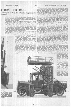
We will now follow through the procedure of transferring the wagon from road to rail. It is first driven over the track until the track wheels are immediately above the lines, and the weight-carrying levers of the rear axle are then forced down and pinned into position ; meanwhile the engine is running free.
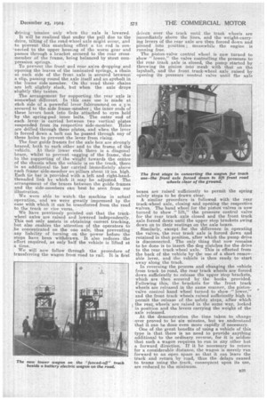
The piston-valve control wheel is now turned to show." lower," the valve controlling the pressure to the rear track axle is closed, the pump started by throwing its pinion into mesh with that on the layshaft, and the front track-wheel axle raised by opening its pressure control valve until the axle boxes are raised sufficiently to permit the spring safety stops to be drawn clear. A similar procedure is followed with the rear track-wheel axle, closing and opening the respective 'valves. The hand wheel for the piston valves is now turned to show •" lift," the pressure control valve for the rear track axle closed and the front track axle forced down until the upper stop brackets swing down on to their seatings on the axle boxes. Similarly, except for the difference in operating the valves, the rear track axle is forced down and retained in that position, after which the pump drive is disconnected. The only thing that now remains to be done is to insert the dog clutches for the drive to the rear track-wheel axle. This is effected from the back of the vehicle by the use of a short removable lever, and the vehicle is then ready to start away along the track. In reversing the process and changing the vehicle from track to road, the rear track wheels are forced down sufficiently to release the upper stop brackets, which are then secured by the hooks provided. Following this, the brackets for the front track wheels are released in the same manner, the piston valve control hand wheel turned to show "lower," and the front track wheels raised sufficiently high to permit the release of the safety stops, after which the rear, wheels are raised in the same way, locked in position and the levers carrying the weight of the axle released.
At the 'demonstration the time taken to change over proved to be six minutes, but We understand that it can he done even more rapidly if necessary.
One of the great benefits of using a vehicle of this type is that there is no need to provide anything additional to the ordinary reverse, for it is seldom that such a wagon requires to run in any other but a forward direction. If it be necessary to return for a considerable distance, the wagon is merely \run forward to an open space so that it can leave the track and return by road, thus the delays caused to trams using the track, consequent upon its use, are reduced to the minimum.