


The " Mero " Speed-changing Device.
Page 24
Page 25
If you've noticed an error in this article please click here to report it so we can fix it.
An Ingenious Arrangement for Enabling Sliding Gears to be Changed Silently and Without Damage.
Among the various change-speed gears and devices which were fitted to whicles at the recent Olympia Show, the most interesting was undoubtedly that exhibited by Mero, Limited, of 8, Albion House, 59 to 61, New Oxford Street, W. This device, to which we Itave made other references on the 7th November, 1907, is not in itself a change-speed gear, but an arrangement which may be added to any exisiting type of sliding gearbox. It may also be embodied in new designs, as is illustrated on this and the following page. The object of this invention is entirely to disconnect the sliding change-speed gears, and the shafts on which they are mounted, while the change from one gear to another is being effected ; a positive clutch is introduced behind the gearbox to do this, and this clutch is so designed as automatically to engage, without shock, after the change in the speed gearing has been effected. It will be readily understood that such an .arrangement, successfully carried out, will obviate all trouble in gear changing, and will prevent all damage to the corners of the gear teeth, because all these wheels are stationary whilst the changing of the speeds is being effected.
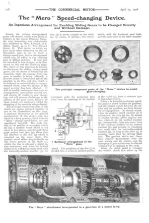
The principal component parts of this clutch are shown grouped together in one of the illustrations on this page. A sectional illustration of the general .arrangement of this device, and two views of a lorry gearbox, fitted with the -" Mero " change-speed device, are also reproduced herewith. The male portion of the positive or secondary clutch .(7) has a toothed wheel which is cut away in two places, and through these gaps project two pins (9); these pins are attached to the disc (5) which is mounted on the same shaft. The toothed wheel slides longitudinally on the driven portion of the shaft (4), whilst the disc is allowed a slight rotary movement, and, when the toothed c hitch (7) is withdrawn from mesh with the internally-toothed member (3), the movement pulls the projecting pins away from the openings in the toothed wheel. The periphery of the disc (5) is divided into a series of inclined planes, of the clutch (2), form a common type of free-wheel clutch.
When it is desirable to change speed, the positive clutch behind the gearbox, and the friction clutch between the engine and the gearbox, are both thrown out of engagement. As already stated, when the positive clutch member (7) is withdrawn, the pins (9) are, by means of tension springs, given angular motion relatively to the toothed member (7); consequently, these pins move clear of the cut-away portions of the toothed member (7), and pret ent its returning into mesh with the internally-toothed member (3), so long as the shaft (4) is running faster than the driving shaft (to). The gearbox shafts are, therefore, entirely disconnected from the road wheels and the engine, and the changing of gear ratios may be effected without fear of damage to the teeth. When the clutch pedal is released, the friction clutch first takes up the
chive, and transmits it, through the shaft (to) and one or other of the change-speed gears, to the sleeve (ii) and the clutch members (I, 2, and 3). When the peripheral speed of the clutch members (t, 2, and 3) exceeds the peripheral speed of the disc (5), the following movements take place in the order given : (a), the steel balls on the outside of this disc are driven up the inclines, and they tend to lock the members (2 and 5) together ; (b), when this happens, the disc (5) moves relatively to
the toothed wheel (7); (c), the pins (9) come opposite to the spaces in the toothed member (7); and (d), the latter member is then allowed to engage with the internally-toothed member (3) at the precise moment when the two members are running at the same speed..
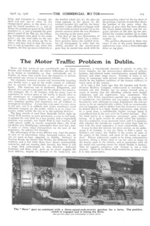
The first of the two illustrations of the " Mem " gear fitted into a motorlorry gearbox shows the toothed member (7) disengaged, in order that the eliding member of the second-speed gear may be moved into mesh with its corresponding wheel on the lay shaft of the gearbox; and the second view shows the position of the parts when the. change of gear ratio has been effected, the clutch pedal released, and the angular advance of the pins (9) has permitted the toothed member (7) to enter into mesh with the internally-toothed member (3). The gearbox illustrated in these two. views is one of the usual three-speedand-reverse type, with a direct-throught drive on top gear.