


What Semi-conductor Devices Mean
Page 62
Page 65
If you've noticed an error in this article please click here to report it so we can fix it.
By David Gurwicz, B.Sc.(Hons)
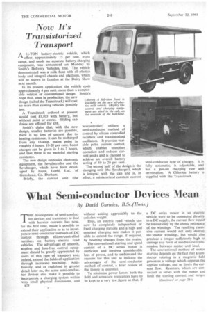
THE development of semi-conductor devices and transistors to deal with heavier currents has now, for the first time, made it possible to extend their application so as to incorporate semi-conductor methods of DC control through silicon-controlled rectifiers on battery electric road vehicles. The advantages of smooth, stepless and loss-free control equipment should be greatly appreciated by users of this type of transport and, indeed, extend the fields of application through increased flexibility. Additionally, and as explained in greater detail later on, the same semi-conductor devices also make it possible to incorporate a charging system within very small physical dimensions, and
n28 without adding appreciably to the unladen weight.
Thus, an electric road vehicle can now be completely independent of fixed charging stations and a high and constant charging rate makes it possible to extend the range, if required. by boosting charges from the mains.
The conventional starting and speed control of a DC series motor is inefficient and involves considerable loss of power, and to understand the reasons for this and to indicate the advantages of the semi-conductor method of control, a brief review of the theory is essential.
To minimize power losses, both the field and armature resistances have to be kept to a very low.figure so that, if a DC series motor in an electric vehicle were to be -connected directly to a DC supply, the current flow would be limited only by the ohmic resistance, of the windings. The resulting excessive current would not only destroy the motor windings, but would also produce a torque sufficiently high . to damage any form of mechanical transmission between motor and load.
The conventional method of motor starting depends on the fact that a conductor rotating in a magnetic field generates a voltage which opposes the applied voltage, and so limits the cur-rent flow. Resistors, which are connected in series with the motor and limit the starting current and torque to reasonable proportions, are withdrawn in stages as the motor gains speed. Once full speed has been attained, the external resistors are completely short-circuited.
Each time the motor starts, external resistances, which are approximately 10 times as high as motor resistance, are inserted, so that 10 times as much power is wasted in resistance losses as is usefully consumed turning the motor, and during the course of a day the total power lost may, in some cases, amount to as much as 25 per cent. of the total power consumption of a battery-electric vehicle.
Disadvantage
Another disadvantage of conventional control is that the external resistors are removed in a series of steps, so that the motor is accelerated in jerks. This means that " inching " control, highly desirable on all batteryelectric vehicles and essential to electric fork-lift trucks, can only be obtained by switching the motor on and off, with subsequent shocks to the transmission. Methods have been devised to minimize the power loss, the most notable being the parallel-series control system developed some 15 years ago by Associated Electrical Industries, Ltd., in association with Smith's Delivery Vehicles; Ltd. However, a method by which loss-free, as well as smooth. stepless control can be obtained is by means of the Sevcontroller.
It is based on the new high-capacity silicon-controlled rectifier (S.C.R.) and is the outcome of an intensive research programme carried out by Joyce, Loebl and Co., Ltd., in collaboration with the world licensees and patentees, Sevcon Engineering, Ltd. The S.C.R., which is analogous to the grid-controlled mercury arc rectifier, is a device having three terminals which, for simplicity. may be called anode, cathode, and gate. When_a voltage is applied across the anode and cathode, the S.C.R. will form an open circuit unless a small signal is applied to the gate, whereupon the device becomes a short circuit capable of carrying large currents with a negligible voltage drop.
Unbroken
The short circuit cannot be broken by terminating the gate signal—to turn off the S.C.R. it is necessary to reduce for a specified length of time the applied voltage between anode and cathode, or to reverse its polarity.
By making use of these devices, and of the inductive nature of the motor series field, the mean current flow in the motor can be controlled. The motor is connected across the DC supply in series with' an S.C.R.. which is "turned on" by a tmlse supplied by a transistorized relaxation oscillator.
Due to the inductive nature of the motor field, the motor current rises only gradually (in this context we are considering time in thousandths of a second) and before it has attained a dangerously high level, a second S.C.R. is fired by a separate oscillator. This second unit discharges a capacitor across the main S.C.R., which is thereby turned off. In order to prevent jerkiness and the possibility of excess voltage, a diode is connected across the motor which allows the current flow to continue in the motor although no current is taken from the source of supply. This current flow is not constant but decreases from the instant the main S.C.R. is switched off.
The cycle is now complete, and may be repeated by successive firings ot the main S.C.R. The repetitive rate, and hence the mean current flowing in the motor, is determined by the frequency of the relaxation oscillator, which is controlled by the operator. In this way, stepless, loss-free control, with infinitely gradual acceleration from rest to full speed. is obtained.
More Current Flows
Since current continues to flow in 'the motor during the inter-pulse periods, it follows that more current must flow than is taken from the battery supply. This is achieved by an automatic current-voltage transformation in the system, which enables starting currents of 200 amps in the motor to be obtained from a supply current of 20 amps. Since torque is proportional to the square of current, very high starting torques can be obtained with a minimum drain on the battery supply.
The units at present under development are capable of handling motor currents up to 600 amps on starting, at 70-80 v. To prevent the slight dissipation experienced in the electronic components on the high power units, a contactor is arranged to short out the controlling circuit once the motor has attained full speed.
, The problems associated with the charging of a large lead-acid accumulator are due to its low internal resistance and to the rise in open circuit voltage during charging. The output voltage of the charger must at least equal the fully charged battery voltage. Extremely heavy currents would flow when the battery is discharged, and might result in damage to the charger --,or more likely in localized heating in the battery. The most common method Of avoiding these dangers is to connect, in series, a resistor or choke to taper the
charging current as the battery terminal voltage rises. The disadvantage of this method is that whilst the average charging current over the whole period is less than the maximum current required, the charging circuit must be capable of supplying the maximum, possibly for an extended period. As a result, the charger is too large and heavy to be carried on a batteryelectric vehicle.
Smaller and Lighter The Sevcharger, incorporating silicon diodes and a silicon-controlled rectifier which delivers a constant current charge, is much smaller and lighter than the conventional type of charger. It may be carried with ease aboard the vehicle, and plugged into a convenient mains supply point at any time for recharging. Where required, the charging system can be combined and housed with the controller in one, single unit. By means of a suitable change-over switch, the same S.C.R.s can be employed for both duties.
The silicon diodes rectify the alternating mains voltage to produce a series of half-sine waves. An S.C.R., connected between the battery and the diodes, is fired at varying points on the output wave form by means of a transistorized relaxation oscillator. The precise point of firing, and hence the voltage applied across the battery, is determined by the magnitude of the R.M.S. current flowing into the battery.
Constant Current
The charging current is thus kept constant, independent of both battery voltage and mains fluctuations, and since it is R.M.S. rather than mean current which determines the heating effect in the battery and the loan on the mains, its constant control offers considerable advantage.
The charger incorporates automatic reduction of the charging rate once the battery voltage has reached a predetermined value, as well as eventual termination of the charge after a fixed period on the reduced rate has elapsed. It may easily be adjusted to give a slow equalizing charge. Chargers for currents up to 25-35 amps at nominal battery voltages of up to 72 v. have now been developed.
While, for the moment, the new devices will be incorporated in batteryelectric road vehicles, there is no doubt that this development may lend itself to many other applications in the electric traction and DC transmission fields. A further development is in progress to explore the wider possibilities of the principle, with a view to exploiting the great potential which is anticipated at home and overseas.