


A Power Take-off Attachment
Page 36
If you've noticed an error in this article please click here to report it so we can fix it.
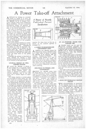
ADEVICE for fitting to a normal vehicle to enable it to drive an auxiliary mechanism is shown in patent No. 562,974, by Al. 0. Harper, Ltd.,
and G. Harper, both of 19, Commercial Road, Guildford. The unit is mounted immediately behind the gearbox, so that the whole range of ratios is available to the driven mechanism.
The unit is contained in a casing which is fitted to a convenient cross member on the frame as, for example, by means of a bolted-on flange (1). The shaft (2) from the gearbox enters
the casing where it is supported by balland-roller bearings, The output shaft (3) continues to the rear and is ultimately re-connected to the propeller shaft of the vehicle.
The power-output member is a multi. grooved pulley (4) journalled on the casing on bearings (5). Attached to the pulley is a set of dog-teeth (6), whilst a similar set is formed on the output shaft (3). Shaft 2 is splined and carries a sliding dog (7) which can be moved by a rod (8) into mesh with either the main drive or the pulley teeth (6).
Although the scheme is .described as being suitable for driving a large dynamo carried by the vehicle, its scope is not limited to this application.
UNUSUAL DESIGN OF TWOSTROKE ENGINE
I N patent No. 362,964 is shown a novel design for a two-stroke engine by W. Quilter and J. Wilkerson, Ley Green, King's Walden, Herts. The engine is claimed to possess a high thermal efficiency, due to low heat losses and a certain degree of supercharge.
The design employs a normal piston moving inside an outer piston (1), The latter works in a normal cylinder, but the cranks are in opposition, giving a total displacement of double the throw.
• In operation, the fuel charge is drawn in through an automatic spring-loaded valve (2) which closes at the end of the' suction stroke. On the up stroke of the outer piston the charge is compressed, during which time the inner piston is descending on its power stroke. At the end of this stroke a transfer valve (3) is forced open by striking the head of the valve (2) and the compressed charge is then blown into the inner combustion space. The incom ing charge descends upon the burnt gases, which, by this time, have mostly escaped through the aligned ports 4 and 5.: The ignition device is rather complex, the sparking plug consist ing of a stationary part (6) and a. movable A LORRY-TO-ROAD-ROLLER CONVERSION UNIT
ASIMPLE but effective means for temporarily using a standard lorry as a road roller is shown in patent No. 562,316, by R. Sparkes, 199, The Avenue, Sunbury-on-Thames. The apparatus used consists of a pair of rollers mounted on a low frame; the lorry is run on to the rollers, coining to rest with its rear wheels between them. The rollers are each divided into two, so as to permit differential movement when cornering.
ONE-PIECE FLYWHEEL AND CRANKSHAFT
PATENT No. 562,825 comes from Singer Motors, Ltd., and L. Shorter, both of Canterbury Street, Coventry, and discloses a scheme for forming the crankshaft and flywheel of an engine in one piece. Actually, the scheme is shown applied to a small engine of only 6 h.p., hut the invention is not, it is stated, limited only to this.
• The assembly is cast in alloy iron, chosen for its good wearing properties, which also make it suitable for the friction face of the clutch. The fact that the flywheel can be machined at the same setting as the main journals simplifier manufacture. AN -ALL-PURPOSE CRANE FOR GARAGE USE
ACRANE which can be used for general workshop purposes, for loading and unloading vehicles, and as a high-lift jack, is shown in patent No. 562,943 from F. Rolph and Wickham Engineering Co., Ltd., 34, Victoria Street, London, SAVA.
The crane is built upon a triangular frame having two wheels at the ends (1) and a pair at the steering end (2). The steering-wheel spindle is eccentrically mounted, and when the handle (3) is in the position shown, the wheels are moved upwardly far enough to transfer the load to the castors (4) . These are arranged to lock solid under heavy load and thus prevent the crane from shifting.
The angle of the jib is adjustable by means of a pair of tension bars (5), which can he pinned to varying effective lengths. The high-lift jack consists of a folding arm (6) which can be extended into the horizontal position, as shown.
A BUILT-UP HYDRAULIC MASTER PISTON
THE non-availability of aluminium and kindred metals is the reason for a modified design of master piston shown in patent No 562,789, by Bendix Aviation Corporation, South Bend, Indiana, U.S.A. The patent describes a design which is suitable for fabrication in sheet steel.
One of several schemes is shown in the drawing; in this 'case the body portion (1) is formed by blanking, followed by a series cif deep drawing operations The flange (2) is upset, whilst the other one (3) is separately made and attached by welding. An inserted solid plug (4) is provided to receive the thrust of the ball-ended actuating rod. An alternative scheme shows a piston designed to be moulded in plastic material.