


Resilient Drive for Injection Pumps
Page 68
If you've noticed an error in this article please click here to report it so we can fix it.
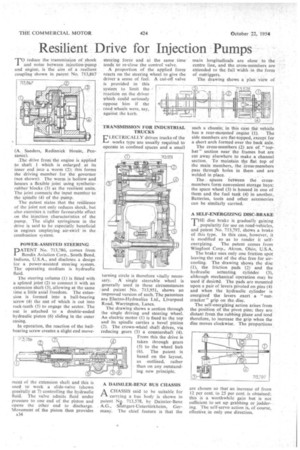
T0 ieduce the transmission of shock and noise between injection-pump and engine, is the aim of a resilient coupling shown in patent No. 713,867
(A. Sanders, Redinnick Houk, Penzance).
.The drive from the engine is applied to shaft 1 which is enlarged at its inner end into a worm (2); this forms the driving member for the governor (not shown): The worm is hollow and houses a flexible joint using syntheticrubber blocks (3) as the resilient units. The joint connects the input member to the spindle (4) of the pump.
The patent states that the resilience of the joint not only reduces shock, but also exercises a rather favourable effect on the injection characteristics of the pump. The slight springiness in the drive is said to be especially beneficial in engines employing air-swirl in the combustion system.
POWER-ASSISTED STEERING DATENT No. 713,786, comes from Bendix Aviation Corp., South Bend, Indiana, U.S.A., and discloses a design for a power-assisted steering system. The operating medium is hydraulic fluid.
The steering column (1) is fitted with a splined joint (2) to connect it with an extension shaft (3), allowing at the same time a little axial freedom. The extension is formed into a ball-bearing screw (4) the nut of which is cut into rack-teeth (5) to engage the sector. The nut is attached to a double-ended hydraulic piston (6) sliding in the outer casing.
In operation, the reaction of the ballbearing screw creates a slight end move meat of the extension shaft and this is used to work a slide-valve (shown generally at 7) controlling the hydraulic fluid. The valve admits fluid under pressure to one end of the piston and opens the other end to discharge. Movement of the piston then provides A34 steering force and at the same time tends to re-close the control valve.
A proportion of the applied force reacts on the steering wheel to give the driver a sense of feel. A cut-off valve is provided in this system to limit the reaction on the driver Which could seriously oppose him if the road wheels were, say, against the kerb, TRANSMISSION FOR INDUSTRIAL TRUCKS
ELECTRICALLY driven trucks of the works type are usually required to operate in confined spaces and a small
turning circle is therefore vitally necessary. A single steerable wheel is generally used in these circumstances and patent No. 713,951, shows an improved version of such. The patentees are Electro-Hydraulics Ltd., Liverpool Road, Warrington, Lancs.
The drawing shows a section through the single driving and steering wheel. An electric motor (1) is fixed to the top and its spindle carries a bevel pinion (2). The crown-wheel shaft drives, via reducing gears (3) a countershaft (4). From this the drive is taken through gears (5) to the wheel hub (6). The patent is based on the layout, as outlined, rather than on any outstanding new principle.
A DAIMLER-BENZ BUS CHASSIS
A CHASSIS said to be suitable for carrying a bus body is shown in patent N2. 713,578, by Daimler-Benz A.G., Sruttgart-Unterttirkheim, Germany. The chief feature is that the
main longitudinals are close to the centre line, and the cross-members are extended to the full width in the form of outriggers.
The drawing shows a "plan view of such a chassis; in this case the vehicle
has a rear-mounted engine (1). The side members are flat-topped, except for a short arch formed over the back axle.
The cross-members .(2) are of " tophat " section near the frames but are cut away elsewhere to make a channel section. To maintain the flat top of the main members, the Cross-members pass through holes in them and are welded in place.
The spaces between the crossmembers form convenient storage bays; the spare wheel (3) is housed in one of them and the fuel tank (4) in another. Batteries, tools and other accessories can be similarly carried.
A SELF-ENERGIZING DISC-BRAKE
THE disc brake is gradually gaining popularity for use on road-vehicles, and patent No. 713,797, shows a brake of this type. In this case, however, it is modified so as to render it self
energizing. The patent comes from Wingfoot Corp., Akron, Ohio, U.S.A.
The brake uses only one friction spot leaving the rest of the disc free for aircooling. The drawing shows the disc (1), the friction pads (2) and the hydraulic actuating cylinder (3), although mechanical operation may be used if desired. The pads are mounted upon a pair of levers pivoted on pins (4) and when the hydraulic cylinder is energized the levers exert a " nut-, cracker " grip on the. disc.
The self-energizing action arises from the position of the pivot pins; they are distant from the rubbing plane and tend therefore, to increase the grip when the disc moves clockwise. The propprtions
are chosen so that an increase of from 12 per cent. to 25 per cent, is obtained; this is a worthwhile gain but is not sufficient to set up grabbing or judder-. ing. The self-servo action is, of course, effective in only one direction.