


frrn, Drivers &Mechanics
Page 19
If you've noticed an error in this article please click here to report it so we can fix it.
TEN SHILLINGS WEEKLY is paid for the best communication received, and one penny a line of ten words for anything else published, with an allowance for photographs.
Send us an account of any sPeciad incident of your work or experience. If suitable, we will edit your notes, suPPly a sketch when required, and pay you for everything published. Mention your emPloyer's name, in confidence, as evidence of good faith. A ddress to The Editor, THE COMMERCIAL MOTOR, Rosebery Avenue, London, E.G.
Light Up Your Lamps At —
5.53 on Thursday ; 5.50 on Friday ; 5.48 on Saturday; 5.45 on • Monday ; 5.43 on Tuesday ; 5.42 on Wednesday.
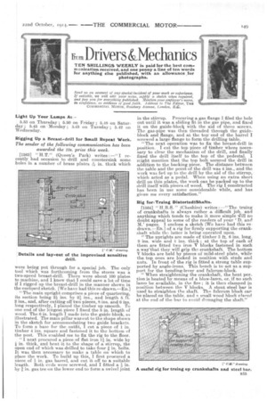
Rigging Up a Breast-drill for Small Repeat Work. The sender of the following communication has been awarded the 10s. prize this week.
[15631 " H.T." (Queen's Park) writes :—" I recently had occasion to drill and countersink some holes in a number of brass plates in. thick which
were being put through for a special job. The only tool which was forthcoming from the stores was a two-speed breast-drill. There were about 100 plates to machine, and I knew that I could save a lot of time if I rigged up the breast-drill in the manner shown in the enclosed sketch. [We have had this re-drawn.—En.] "The main upright comprises a piece of quartering, its section being 2i ins. by 4 ins., and length 5 ft. 2 ins., and, after cutting off two pieces, 8 ins. and 6 ins. long respectively, I planed the timber up smooth. To one end of the longest piece I fixed the 8 in. length of wood. The 6 in. length I made into the guide-block, as illustrated. The main pillar was cut to the shape shown in the sketch for accommodating two guide brackets. To form a base for the outfit, I cut a piece of 1 in. timber 4 ins. square and fastened it to the bottom of the post. This enabled me to fix the: rig to the floor.
"I next procured a piece of at iron 11 in. wide by
in. thick, and bent it to the shape of a stirrup, the open end of which was drilled to take four in. bolts, It was then necessary to make a table on which to place the work. To build up this, I first procured a niece of 5i in. gas barrel, and cut it off to a suitable length. Both ends were screwed, and I fitted a 4 in. by 1. in. gas tee on the lower end to form a swivel joint in the stirrup. Procuring a gas flange I filed the hole out until it was a sliding fit in the gas pipe, and fixed it on the guide-blocli with the aid of three screws. The gas-pipe was then threaded through the guideblock and flange, and at the too' end of the barrel I screwed a large flange to form the drilling table.
"The next operation was to fix the breast-drill in position. I cut the top piece of timber where necessary to clear the mechanism of the drill, and finally fixed the drill itself to the top of the pedestal. I might mention that the top bolt secured the drill in addition to the backing piece. The distance between the table and the point of the drill was 4 ins., and the work was fed up to the drill by the aid of the stirrup, which acted as a pedal. When using an extra short drill on thin plates, the work can be packed up to the drill itself with pieces of wood. The rig I constructed has been in use some considerable while, and has given me every satisfaction."
Rig for Truing DistortediiShafts.
11564] " H.B. S. " (Cheshire) writes :—" The truing of crankshafts is always rather a difficult job. and anything which tends to make it more simple ilI no doubt appeal to some of the renders of your ' ancl NV pages. 1 enclose a sketch [We have had this re drawn.—ED.1 of a rig for firmly supporting the crankshaft while a,latter is being operated upon.
"The uprights are made of timber 3 ft. 6 ins, long. 9 ins, wide and 4 ins. thick ; at the top of each of them are fitted two iron V blocks fastened in such a way*tbat they will grip th crankshaft. The bottom 17blocks are held by pieces of mild-steel plate, while the top ones are locked in position with studs and nuts. In front of the rig is fitted a strong table supported by angle-irons. This bench is to act as a support for the bending-lever and fulcrum-block.
"When straightening the crankshaft, the bent por. thin is heated by means of a blow-lamp, or, if no such lamp be available, in the fire ; it is then clamped in position between the V blocks. A stout steel bar is used to straighten the shaft. The fulcrum block car be placed on the table, and small wood block placed at the end of the bar to avoid d'imaging the shaft."