


A Swirl-producing Injection Nozzle
Page 46
If you've noticed an error in this article please click here to report it so we can fix it.
FROM Joseph Lucas, Ltd., and E. Watson, both of Great King Street, Birmingham, 19, comes,, in patent No. 578,959, an improved type of fuelinjection nozzle. The object is to prevent the pressure-flow characteristics from being disturbed by the presence of small solid particles in the fuel.
The. drawing shows the tip of the proposed nozzle, the main feature of which is a conical plug (1) provided with u pair of helical grooves (2) along its exterior. The plug is brazed into its surroundings, so that the fuel has to travel through the grooves. It is thus given a strong swirling motion as it emerges into space 3, and foreign particles are thrown to the periphery, leaving the central core of fuel in a clear state. The thin washer 4 is made of hardened steel to resist the erosion of the passing fuel.
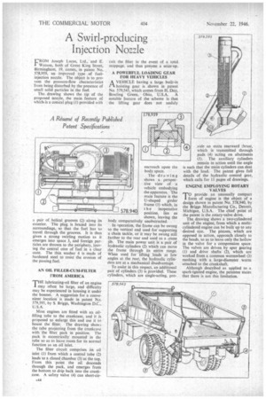
AN OIL FILLER-CUM-FILTER FROM AMERICA
THE Inbricating-oil filter of an engine may often be large, and difficulty may be experienced in housing it under the bonnet. A suggestion for a convenient location is made in patent No. 579,595, by S. Briggs, Washington D.C., U.S.A.
Most engines are fitted with an oilfilling tube to the crankcase, and if is proposed to enlarge this and use it In house the filter. The drawing shows the tube projecting from the crankcase with the filter pack in position. The pack is eccentrically mounted in the tube so as to leave room for its normal function as an oil inlet.
The filter circuit comprises an oil inlet (1) from which a central tube (2) leads to a closed chamber (3) at the top. From this point the oil descends through the pack, and emerges from the bottom to drip back into the crankcase. A safety valve (4) can short-cir
encroach upon the body space.
The drawing shows a perspec• tive view of a vehicle embodying the apparatus. The main feature is the U-shaped girder frame (1) which, in t h e inoperative position, lies as shown, leaving the body comparatively unobstructed.
In operation, the frame can be swung to the vertical and used for supporting a chain tackle, or it may' be swung still farther to the rear and used as a crane jib. The main power unit is a pair of hydraulic cylinders (2) which can move the frame through its entire range. When used for 'lifting loads at low angles at the rear, the hydraulic cylinders are at a mechanical disadvantage.
To assist in this respect, an additional pair of cylinders (3) is Provided. These cylinders, which are single-acting, pro vide an extra rearward thrust, which is transmitted through pads (4) acting on abutments (5). The auxiliary cylinders remain in action until the angle is such that the main cylinders can deal with the load. The patent gives full details of the hydraulic control gear, which calls for 11 pages of drawings.
ENGINE EMPLOYING ROTARY VALVES
T°provide an unusually compact form of engine is the object of a design shown in patent No. 578,940, by the Briggs Manufacturing Co., Detroit, Michigan, U.S.A. The chief point of the patent is the rotary-valve drive.
The drawing shows a two-cylindered unit of the engine, from which a multicylindered engine can be built up to any desired size. The pistons, which are opposed in action, approach closely to the heads, so as to leave only the hollow in the valve for a compression space. The valves are driven by spur gearing (1) and drive shafts (2), which are worked from a common wormwheel (3) meshing with a large-diameter worm attached to the crankshaft.
Although described as applied to a spark-ignited engine, the patentee states that there is not this limitation.