


A NEW BI-FUEL CARBURETTER.
Page 40
If you've noticed an error in this article please click here to report it so we can fix it.
A Résumé of Recently Published Patents.
An invention of more than usual interest is covered by specification No. 169,766, which describes a hi-fuel carburetter which has been patented by E. Dobson. The inventor commences his specification by referring to the important difference which exists between one liquid fuel and another in respect of the temperature at which suitable mixtures of the fuel and air are liable to selfignite. As the temperature of the mixture within the cylinder is largely governed by the degree of compression which ie attained, it follows that the choice of a fuel and the maximum compression of the mixture before ignition must be interdependent. For example, paraffin, owing to its low self-ignition temperature, cannot be used in an ordinary internal-combustion engine in which the compression pressure is great, and, in consequence of this, the efficiency of such engines is not, as a rule, high. The principal object of the present invention is that of providing a multi. fuel carburetting'system in which proper regard has been had to the various selfignition points of the different fuels which are to be used, so that the maximum efficiency is obtainable with each and all of them. With this end in view, the fuel supplies, as to their nature and extent, are so regulated' in the carburetter, which is the subject of the invention, that, by throttling or otherwise, a fuel of low self-ignition temperature, such as paraffin, is employed when the engine compression is low, and a fuel of high self-ignition temperature, such es alcohol, is automatically brought into use when the compression pressure is high.
In one particular case, as a matter of fact, the employment of the fuels in the manner now suggested has been tried, but in that instance the selection of the particular fuel to be used at any time by the engines was determined by a centrifugal governor, so that at high speeds (and, consequently, as a rule, low compressions) paraffin was admitted. Unfortunately, this still left it possible for the low-ignition point fuel to be ad-. mined at low speeds and full throttle opening. As now patented and deecribed, the control of the fuels is by means of the .mixture throttle, the change-over being. effected according to the degree of opening of the said throttle.
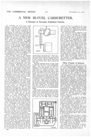
• In this manner the risk of pre-ignition, which would occur in the event of a fuel of low self-ignition point being used at full engine load, is entirely avoided; consequently, there is no need to employ a lower compression pressure than usual. On the contrary, a higher compression than the normal can be employea with advantage, so that both the output, and efficiency of the engine are promoted. Several methods of controlling the fuel supplies are described in the specification. We propose only to deal with one, which is diagrammatically illustrated by the accompanying sketch, which is reproduced from the specification: itself. The principal components of an ordinary carburetter are indicated on the figure, the throttle being shown towards the top of the drawing, the direction of flow of the mixture being from left to right. The arrows•indicate the movement of the 040 various fuels and of the air. Those having no feathers indicate the course of the air only, those with one feather that of a fuel mixture, while those with more than one feather show the movement of fuel only.
The float chamber shown is that which is used for the fuel of low self-ignition point. The fuel, , it will be observed, emerges from the chamber by way of a submerged jet which is located at the lower end of a vertical split tube. Onehalf of the upper end of the tube is open to the atmosphere; the other leads to a choke tube in a narrow vertical pipe. The arrangement is such that, as fuel is drawn through the submerged jet, it is accompanied by a proportion of air which is sucked in with it from the open end of the tube. This causes an emulsion of air and fuel to be formed and supplied to the small choke tube. The pipe in which the small choke tube is located opens into the main inlet to the carburetter, and is surrounded by an exhaust-heated jacket.
The length of. the small pipe and the relative areas of its choke tube and that of the main carburettor are such that a critical velocity is reached in the small choke before the same thing occurs in the large one, so that, after a certain
velocity of flow is reached in the main choke tube, the supply from the small one commences to decrease in quantity. This controls the supply of the fuel of low self-ignition point. The alternative fuel is supplied to the main carburetter through the passage which is seen, on the drawing, to enter the main choke tube at a point immediately opposite that at which the other fuel enters. It is controlled by a stopcock or other means, the lever for which is connected to the main throttle lever in such a way that supply of the fuel of high ignition point is prevented until the throttle is opened more than a predetermined amount. Additional supplies of this fuel are available, at full throttle opening, when it may be desirable to enrich the mixture, through the pipe which is seen in the drawing: to 'approach the throttle valve on the angle, while the third pipe, depicted vertically above the throttle valve, is for the purpose of providing a supply of petrol or other easily volatilized fuel for starting purposes.
Other Patents of Interest.
An improvement in that type of engine in which the exhaust gases from one ' or more high-pressure cylinders are passed into a low-pressure cylinder, in which they are further expanded and in which they do useful work, is described in specification No. 169,799 by W. G. Germandt. In this case there is, in one with the engine, a pair of high-pressure cylinders, arranged one on each side of a low-pressure cylinder. All three cylinders opezate on the same crankshaft, the crank pins of the high-pressure cylinders being ranged at 180 degrees to that of the low-pressure cylinder. The high-pressure cylinders operate on the four-stroke principle, while the low-pressure operates on the two-stroke, The mixture is first compressed in the crank chambers of the high-pressure cylinders, then further compressed in the crank chamber of the low-pressure cylinder, and finally compressed in the low-pressure cylinder before being transferred to the highpressure cylinders.
No. 169,774, by J. and B. Oldfiekl, Ltd.' describes a new form of lens for a rear lamp of the type in which a pair of box-like extensions is attached to the lamp and inclined rearwardly for the purpose of directing the beam of light on to the number plate of the car.
Another lamp invention is described in No. 169,779. In this case the front lens of a headlight is formed on the inside of the glass with a number of pimples of special ferm, the object being to reduce the dazzle effect. The patentee is C. G. Smith.
An' improved form of what is known as the Charaphone is referred to in specification No. 169,813, by C. Hyland. An attempt is made to intensify the effect of the instrenent by carrying a quantity of air, collected bv an injector, into the tube whiai conveys the sound.
A simple form of magneto coupling, which is designed also to act. as an impulse starter, is described by M. S. Conner end another in No.. 179,853.