


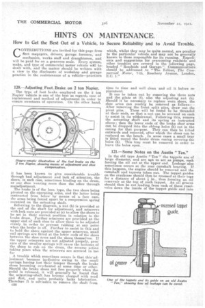
120. — Adjusting.Foot..Brake. on 2 ton Napier. The type of foot brake
Page 38
Page 39
If you've noticed an error in this article please click here to report it so we can fix it.
employed on the 2 ton Napier vehicle is one of the best as regards ease of replacement and method of adjustment in order to ensure sweetness of operation. On the other hand, it has been known to give considerable trouble through bad adjustment and lack of attention, the shoes, in such ease, sometimes binding on the drum, or one shoe wearing more than the other through maladjustmerit. The brake is of the loco, type, the two shoes being pivoted on the operating arms, and the latter being contracted from below by means of a face cam, the arms being forced apart by a compression spring mounted on the actuating shaft. Referring to the diagram, a nut (b) is provided at the end of the shaft for adjustment, and setscrews With lock nuts are provided at (c) to allow the shoes to be set in their correct position in relation to the brake drum. Further setscrews are provided at the ' upper end of each shoe to allow them to be adjusted evenly in order to prevent rubbing at any point when the brake is off. Further to assist in this and to hold the shoes against the upper setscrews, small coil springs are fitted at the lower ends of the shoes between the shoe arms and the shoes themselves. If the upper setscrews are not adjusted propely, pres; sure of the smaller springs will cause the bottoms of the shoes to rub on the drum, the reverse action taking place when the setscrews are screwed in too far A trouble which sometimes occurs is that this'adjustment becomes ineffective owing to the. small springs haying lost their temper through the brake shoes becoming overheated at some time or other. Should the brake shoes not free properly when the pedal is released, it will generally be found that the actaiatings shaft has become clogged with mud and dirt, and quite probably lacks lubrication. Therefore' it is advisable to remove the shaft' from c38 time to time and well clean and oil it before replacement. It can be taken out by removing the three nuts and the plate at (f), also the adjusting nut (b). Should it be necessary to replace worn shoes, the shoe arms can readily be removed as follows:— After removing the front split pins, draw out the pivot pins. These will be found -La be threaded at their ends, so that a nut can be screwed on each to assist in its withdrawal. Following this, remove the actuating shaft and its spring as instructed above; then the lower ends of the brake shoearms can be dropped into the oblong holes (h) cut in the casing for that purpose. They, can then be tilted outwards and removed, after which the shoes can be replaced on the bench. In some cams a small tray is fitted round the brake drum casing covering the holes (h). This tray must be removed in order to leave the holes open.
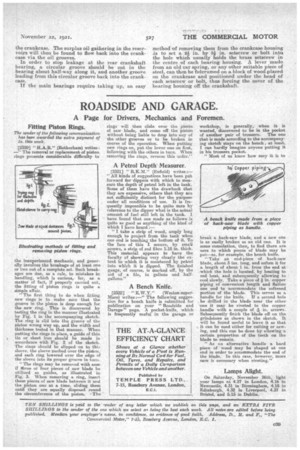
121.—Some Notes on the Austin "Ten."
In the old type Austin " Ten " the tappets are of large diameter, and are apt to act as pumps, each forcing the oil out at the upper end. Leakage also sometimes occurs at the rear camshaft bearing. If this happens, the engine should be removed and the camshaft and tappets taken out. The tappet guides on the crankcase should then be recessed at their taps for a distance of about k in., thus forming an oil reservoir at the top of each tappet. An oil groove should then be cut leading from each of these reservoirs down the inside of the tappet guide and into
the crankcase. The surplus oil gathering in the reservoirs will then be found to flow back into the crankcase via the oil grooves. In order to stop leakage at the rear crankshaft bearing, a circular groove should be cut in the bearing about half-way along it, and another groove leading from this circular groove back into the crankcase.
If the main bearings require taking up, an easy
method cf removing them from the crankcase housing is to set a 211 in. by 84. in. setscrew or bolt intoi the hole which usually bolds the brass setscrew in the centre of each bearing housing. A lever made from an old car spring, or any other suitable piece of steel, can then be fulcrumed on a block of wood placed on the crankcase and positioned under the head of each setscrew or bolt, thus forcing the cover of the bearing housing off the crankshaft.