


Torsion and Compression in Rubber Suspension System
Page 36
If you've noticed an error in this article please click here to report it so we can fix it.
A Résumé of Patent Specifications that Have Recently Been Published
QUSPENSION systems ernplwing
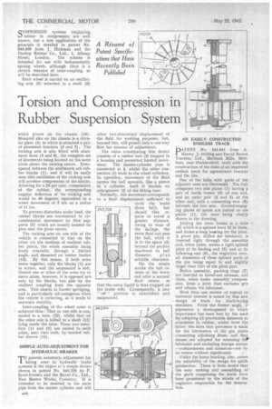
rubber in compression are 4vell known, but a new application of the principle is detailed in patent No. 543,939 from J., Hickman and the Dunlop Rubber Co., Ltd., I, Albany Street, London. The scheme is intended for use with independently sprung wheels, although there is a certain measure of inter-coupling, as will be described later.
Each wheel is carried on an oscillating arm (9) attached to a shaft (6) which pivots on the chassis (10). Mounted also on the chassis is a circular plate (4) to which is attached a pair of abutment brackets (3 and 7). The rocking arm is also fitted with abutment faces (5 and 8), the complete set of abutments being located on the same circle about the rocking centre. Interspaced between the abutments are rubber blocks (1), and it will be easily seen that oscillation of the rocking arm will produce compression of the .blocks. Allowing for a 25 per cent. compression of the rubber, the corresponding angular deflection of the rocking arm would be 40 degrees, equivalent to a wheel movement of 7 ins, at a radius of II ins.
To prevent distortion under load, the rubber blocks are roe strained to circumferential . movement by thin supports (2) which are loosely located on pins near the pivot centre.
The rocking arm on one side of the vehicle is connected to that on the other via the medium of resilient .rubher joints, the whole assembly being freely rotatable, through a limited angle, and mounted on rubber bushes (13). By this means, if both arms move together, only the blocks (1) are in action, and the suspension! is soft. Should one or other of the arms try to move alone, however, it is opposed not only by the blocks, but also by the resilient coupling from the opposite arm. This results in harder springing, and is particularly achantageous when the vehicle is cornering, as it tends to maintain stability.
Inter-coupling of the wheel arms is achieved thus: That or. one side is con; nectecl to a tube (12) , whilst that on the other side is bolted to a shaft (11) lying inside the tube. These two members (11 and 12) are united to each other, near their ends, by bonded rubber sleeves (14),
SIMPLE AUTO-ADJUSTMENT FOR HYDRAULIC BRAKES
'rprovide automatic adjustment for iming wear in hydraulic brake systems is the object of a simple device shown in patent No. 543,729 by P. Scott-Iversen and the Rover. Co., Ltd., New Meteor Works, Coventry. It is intended to be inserted in the main pipe from the master cylinder and will
allow two-directional displacement of the fluid for working purposes, but, beyond this, will permit only a one-way flow for reasons of adjustment.
The valve constituting this device consists of a rubber ball (3) trapped in a housing and permitted limited movement. The master-cylinder pipe is connected at 4, whilst the other connection (I) leads to the wheel cylinders. In operation, movement of the fluid carries the baIl upwards, like a piston in a cylinder, until it reaches an enlargement (2) of the fitting bore.
Normally, this movement corresponds to a fluid displacement sufficient to work the brake shoes fully, but should they require to travel a greater distance, owing to wear of the facings, the extra fluid can pass the ball, while it is in the space (2) beyond the portion machined to hall diameter, plus suitable clearance.
On the return stroke the ball reseats at the lower end after a normal fluid return, so that the extra liquid is thus trapped on the brake side. Consequently, a new " off " position is established and maintained. AN EASILY CONSTRUCTED ENDLESS TRACK DATENT No. 543,941 from A.
Kersey. J. Stirling and David Brown Tractor's, Ltd., .Meltham Mills, Meltham, near Huddersfield, deals with the construction of the links of an improved endless track for agricultural tractors and the like.
One of the links with parts of the adjacent ones are illustrated. The link comprises two side plates (1) having a pair of inside bosses (9) at one end, and an outer pair (3 and 5) at the other end,, with a connecting web (8) between the two sets. Ground-engaging plates or spuds are bolted to the plates (1), the nuts being clearly shown in the drawing.
Joining the inner bosses is a tube (4) which is a splined force fit in them, and forms a long bearing for the joint. A pivot pin, drilled for lubricant, is inserted right through the assembly and, when home, makes a tight splined joint at its leading end (2) and at its following end (6), the respective overall diameters of these splined parts of the pin being equal to and slightly larger than that of the plain part.
Before assembly, packing rings (7) are inserted in bored-out recesses, and these, when under assembly compression, form a, joint that excludes grit and retains the lubricant.
More than one matter of topical or technical interest is raised by this new design of track for track-laying machines. From the former angle, it represents a development to which importance has been lent by the need for adopting all practicable measures to economize in rubber, whilst from the latter, the facts that provision is made for the lubrication of the pin joints connecting adjoining ihoes, and that means are adopted for retaining the' lubricant and excluding foreign matter —containinents and abrasives—are by no means without significance.
Udder the latter heading, also, comes the suitability of the design for quick production. There is little doubt that the easy making and assembling of the parts comprising the track have been prominent in the minds of the engineers responsible for the innovation.