


Is This the Government's Mark II Producer ?
Page 22
If you've noticed an error in this article please click here to report it so we can fix it.
Under the M. of W. T, Scheme, 10,000 Vehicles Would be Equipped with the "Almost Unknown Improved Emergency Producer
F*aFt'STERY surrounds the ao-called 1V1" improved Government Emergency producer," which it is proposed by the Minister of War Transport to manufacture in numbers sufficient for the equipment of 10,000 commercial vehicles. The industry, it seems, is being asked "to buy a pig in a poke."
Little appears to be known, outside official circles, about the design of this apparatus or about its performance, and official circles shut up like the proverbial oyster when asked to disclose any information relating to it.
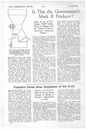
However, one is tempted to think that it may, at least, be based upon an improved device, which emanated from the Fuel Research Station about a year ago, and about which there was no secrecy at the time. The following is a brief description of what may be "Emergency Producer Mark II" and the accompanying drawing illustrates its general construction.
Of considerable technical interest, this producer differs from the original Mark I Emergency design in respect of a basic principle. It is of the downdraught type. So far as we can ascertairi it has been designed primarily as a dry-blast producer, but we understand that, in its present form, it is readily adapted to function on the wet-blast principle.
Another noteworthy feature is that it has a movable grate, which is positioned advantageously for the transference of dust and small matter to the ashbox. The grate can be operated to agitate the substances accumulated upon it, by external means—either by hand or by some moving part of the vehicle.
Heavier • matter follows an inclined path downwards, to a grid, covering the gas off-take which is on the side of the producer opposite to that in which the tuyere is situated. There are two side plates above the moving grate, in planes parallel with the tuyere axis. The purpose of these is to direct the small matter from the vicinity of the tuyere nozzle to the gtate, through which they pass into an ashbox below. Provision is further made for withdrawing spent and partly •spent fuel from the lower part.
It will be observed from the accompanying sketch, which shows the general layout of the apparatus, that the air enters a throat in the producer of relatively small cross-section. We understand that this may have a refractory lining and here will be the zone of highest temperature.
With regard to the moving grate, this is of cylindrical cross-section, with the convex side uppermost, and it co-operates with a fixed portion, of corresponding curvature and set just below it at a suitable distance to permit comparative freedom of oscillation • when it is laden with ash, clinker, etc. There are apertures in the grate itself., and in the fixed co-operating part. Those at the ends of the last-named allow the moving unit to pass through them, sothat oscillation has the effect of sweeping the small substances into the receptacle below.
There does. not seem to be anything particularly outstanding about the tuyere. It is Water-cooled in orthodox manner, deflectors within the jacket enforcing the circulation of the water from end to end.
Among the purposes of the design are the reduction of slag formatioit by the rapid removal of " fines " from the zone immediately below the tuyere. Also it is claimed that by giving the main body of the fuel a relatively slow motion, while maintaining it at temperatures high enough to crack the gaseous products, but not to break down the fuel, conditions are fulfilled for generation of satisfactory gas and good working of the plant.