


THE SCIENCE OF MAKING "APERED ROLLER BEARINGS
Page 42
Page 43
Page 44
Page 45
If you've noticed an error in this article please click here to report it so we can fix it.
Specialized Products of British Timken, Ltd., Tapered-roller Bearings Are Widely Used in Automobile Chassis and for Industrial Purpoes
In Their Manufacture Machines of Great Ingenuity are Employed, Whilst, to Ensure Precision, Highly Accurate Testing Methods are Practised
.1 ..6
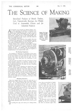
N invitation was extended by British Timken, Ltd., to those attending the Institute of Transport Con gress, in Birmingham this week, to visit its works at Cheston Road, Aston, Birmingham, in order to gain an insight at first hand into the manufacture of roller and ball bearings, especially those of the tapered-roller type, which are a speciality of this concern, and with which its name is generally associated.
. For the benefit of the majority of our readers who were not afforded this opportunity, we are publishing a description of the methods employed by this concern, which we have closely investigated expressly for this purpOse.
British Timken,Ltd., produces tapered-roller bearings in standard sizes from about i in. to over 51. ins, outside diameter, the largest, as a complete double-row bearing, weighing 31 tons. In addition, ball and parallel-roller bearings are made, but, in the main, these are supplied as complementary to the tapered-roller units.
The Bearing Components.
For simplicity in following our description of the manufacturing processes, it should be appreciated that a bearing of this type consists of an outer part (the cup), an inner member (the cone), the rollers and the cage. The raw material from which these parts are constructed is steel rod and tube.
Cups and cones are forged, the ends of the bars or tubes being expanded, opened up, if necessary, shaped by dies to the required formation, and then cut off, these operations being performed with the metal hot and a descaling operation being included.
Rollers under i in. in diameter are formed from steel wire by a process called cold heading. There is a number of machines into which the wire is fed which. form rollers in practically one operation. The wire projects an appropriate distance through the head of the machine, is cut off, the piece is passed to a die into which it is then pressed, and is ejected, the roller emerging, roughly tapered and with radiused edges and recessed ends. Rollers of bigger diameter are forged hot in a vertical press of more or less orthodox design.
Machining Operations.
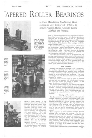
From the forging shop the cones and cups pass to a machine shop, where automatic lathes turn them, roughly, to size. As we passed through this part of the works, small cones, which arrived, in this case, in the form of solid blanks, were being machined. One lathe we watched performed the operations of drilling, boring, surfacing, radiusing, undercutting and parting off ; the last but one is of considerable importance, as it has a big influence on the correct functioning of the bearing.
It is obvious that the maintenance of roller alignment is essential. To preserve this by means of the cage would be unsound ; the Timken method is to employ a rib, which takes the form of a flange around the larger end of the cone. Its face is at slightly more than 60 degrees to the bearing surface, and the rollers are held up against it by the load on the .bearing. In this way, they are kept square with the rib face and, therefore, precisely in line. The undercutting operation forms this 'rib face at the correct angle.
After parting off, cups and cones go to facing lathes, a32 where they are machined to length. A noteworthy point is that airoperated chucks are used on these tools, so that they need not be stopped and started each time the work is put into position and removed. At this stage, every cup and cone is inspected for every dimension, an error not exceeding .008 in. oversize being tolerated. A check so early in the proceedings might he thought unnecessary, but it avoids much needless grinding later on.
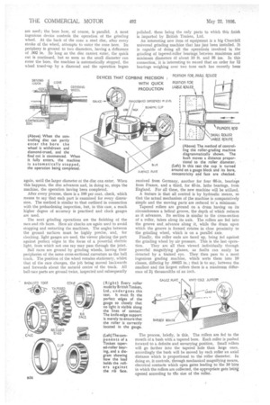
We observed a set of cups being inspected. One check consisted of placing the cup on a cone-shaped die with an accurate upper face, having a lower section. If the dimensions be correct, the die just protrudes, whilst the recessed parts are below the face of the cup. The practised viewer can detect these differences in level by finger touch and can conduct the examination with great rapidity. " Go" and "not go" gauges are used for the other dimensions. Following viewing, the components are marked with the company's name, the part number, etc., in a stamping machine, and pass on to the hardening furnaces.
On our way to this department, we noticed a batch of axle boxes for railcars and paused to examine them. A feature which attracted our attention was the surface of the bores of the boxes. It is Timken practice to grind this part in which the bearing cups fit. The concern also lines the horn guides with manganese-steel liners, and informed us that the life of such an axle box, equipped with dual-row • 10-in.-diameter 4-in, bearings, would be about 1,000,000 miles.
The tapered-roller-bearing components are carburized in the furnaces for a period, depending upon the size of the beating and the depth of case required. It may possibly be so long as a week. The rollers, however, go through comparatively quickly. The furnaces are gas-fired and the temperature electrically controlled.
For testing the hardening, some of the rejects from the previous inspection are carburized in marked pots, quenched in water and immediately afterwards broken for examination of the fracture. Some samples were undergoing this test on the occasion of our visit to the hardening shop, and an inspection of the fracture appeared to reveal to the naked eye a practically perfect structure.
'Heat Treatment.
Normally, the sequence of operation is this. Carburizing, slow cooling, unpacking from the pots, reheating, oil quenching for refining the core reheating, water quenching for surface hardening, and tempering in oil to remove stresses set up by machining and hardening. The water quenching is done with the component on a die to prevent distortion or warping.
Afterwards, every cone and cup is file tested by hand for soft spots and then examined with a clock gauge to ensure that it has not become oval, shrunk or grown. At this stage, the tolerance permitted is .004 in.
The bearings are now ready for final grinding, and a large area of the works is devoted exclusively to the operations involved. The shop is divided into two sections, one for cups and one for cones. Each operation is performed by a number of machines in a bay, and adjoining each row of machines is a caged-off room, where the parts are inspected.
Grinding to Fine Limits.
The. first operation, for which Blanchard face grinders are used, is finishing the ends of the cups and cones; they are then demagnetized and examined. The outside diameters are ground on Churchill centreless machines, the accuracy here being to .0006 in. The cups are fed in an axial direction to the grinding wheel on guides and are held against the wheel by a drum set slightly -ant of alignment so that the feed is automatically applied and a tendency for the cups to advance along the guides is created.
Bores are ground on Heald Sizematic machines, the small grinding wheel oscillating and rotating. The first cut increases the bore to .002 in. undersize. The wheel is then diamond-trued and the bore ground to exact size. After each batch has been thus treated, the grinding wheel is changed and a final fine grind, in which no appreciable metal is removed, takes the place of the alternative, which would be to polish the metal. No actual polishing is done, however, as its effect is to conceal any flaw that might otherwise be revealed,
In the case of the cone bores, Heald Gagematic machines n:33
are used ; the bore here, of course, is parallel. A most ingenious device controls the operation of the grinding wheel, At the back of the cone a steel disc, after every stroke of the wheel, attempts to enter the cone bore. Its periphery is ground to two diameters, having a difference of .002 in. So long as the disc cannot enter, the quick cut is continued, but so soon as the small diameter can enter the bore, the machine is automatically stopped, the wheel trued-up by a diamond and the operation begun again, until the larger diameter at the disc can enter. When this happens, the disc advances and, in doing so, stops the machine, the operation having been completed.
After every process, there is a 100 per cent, check, which means to say that each part is examined for every dimension. The method is similar to that outlined in connection with the prehardening inspection, but, in this case, a much higher degree of accuracy is practised and clock gauges are used.
The next grinding operations are the finishing of the race and rib faces. Here air chucks are again used to avoid stopping and restarting the machines. The angles between the ground surfaces must be highly precise, and, for checking, light gauges are used, the viewer placing the part against perfect edges in the focus of a powerful electric light, from which not one ray may pass through the joint.
Ball races are ground by grinding wheels, having their peripheries of the same cross-sectional curvature as the ball track. The position of the wheel remains stationary, whilst that of the race changes, the job being moved backwards and forwards about the natural centre of the track. All ball-race parts are ground twice, inspected and subsequently polished, these being the only parts to which this finish is imparted by British Timken, Ltd.
An interesting new item of equipment is a big Churchill universal grinding machine that has just been installed. It is capable of fining all the operation's involved in the grinding of tapered-roller bearings. betweenmaximum and minimum diameters 61 about 10 ft. and 36 ins.. In this connection, it is interesting to record that an order for 12 bearings weighing over two tons each has recently been
received from Germany, another for four 66-in, bearings from France, and a third, for 43-in, lathe bearings, from England. For all these, the new machine will be utilized.
A feature is that all control is by hydraulic means, so that the actual mechanism of the machine is comparatively simple and the moving parts are reduced to'a minimum.
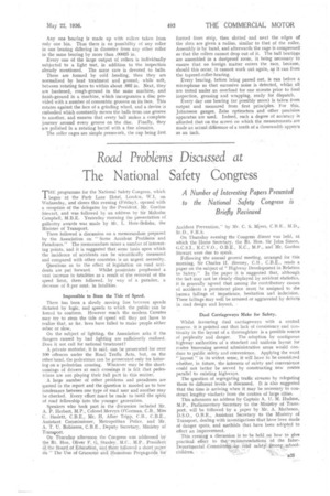
Tapered rollers are ground on a drum having on its circumference a helical groove, the depth of which reduces as it advances. Its section is similar to the cross-section of a roller, taken along its axis. The rollers are fed into the groove and, advance along it, while the drum upon which the groove is formed rotates in close proximity to the grinding wheel, which is on a parallel axis.
Finally, the roller ends are faced up, being fed against the grinding wheel by air pressure. This is the last opera tion. They are all then viewed individually through powerful magnifying glasses, as faults can easily be detected by a trained eye. They then pass to a most ingenious grading machine, which sorts them into 10 classes, differing by .00025 in. ; that is to say, between the. smallest and the largest rollers there is a maximum difference of 21 thousandths of an inch.
The process, briefly, is this. The rollers are fed to the mouth of a bush with a tapered bore. Each roller is pushed forward to a definite and unvarying position. Small rollers will go farther into the tapered hole than large ones, accordingly the bush will be moved by each roller an axial distance which is proportional to the roller diameter. In doing so, it controls, through mechanical magnifying means, electrical contacts which open gates leading to -the 10 bins in which the rollers are collected, the appropriate gate being opened according to the size of the roller.
Any one bearing is made up with rollers taken from only one bin. Thus there is no possibility of any roller in one bearing differing in diameter from any other roller in the same bearing by more than .00025 in.
Every one of the large output of rollers is individually subjected to a light test, in addition to the inspection already mentioned. The same care is devoted to balls.
These are formed by cold heading, then they are normalized by heat treatment and ground, while soft, between rotating faces to within about .002 in. Next, they are hardened, rough-ground in the same machine, and finish-ground in a machine, which incorporates a disc provided with a number of concentric grooves on its face. This rotates against the face of a grinding wheel, and a device is embodied which constantly moves the balls from one groove to another, and ensures that every ball makes a complete journey around every groove on the disc. Finally, they are polished in a rotating barrel with a fine abrasive.
The roller cages are simple presswork, the cup being first
formed from strip, then slotted and next the edges of the slots are given a radius, similar to that of the roller. Assembly is by hand, and afterwards the cage is compressed so that the rollers cannot drop out of it. The ball bearings are assembled in a dustproof room, it being necessary to ensure that no foreign matter enters the race, because, should this occur, it cannot work out again, as it can from the tapered-roller-bearing.
Every bearing, before being passed out, is run before a microphone so that excessive noise is detected, whilst all are tested under an overload for one minute prior to final inspection, greasing and wrapping, ready for dispatch.
Every day one bearing (or possibly more) is taken from output and measured from first principles. For this, Johansson gauges, Zeiss optimeters and other precision apparatus are used. Indeed, such a degree of accuracy is afforded that on the screen on which the measurements are made an actual difference of a tenth of a thousandth appears as an inch.