


AN OIL-FUEL BURNER FOR STEAM WAGONS.
Page 34
If you've noticed an error in this article please click here to report it so we can fix it.
A Résumé of Recently Published Patents.
AN OIL-FUEL burner for steam wagons, and an anti-pinking fitting for carburetters, by the use of which higher compression pressures on petrol engines may be made practicable, are the leading features of interest, in this week's patent specifications. .
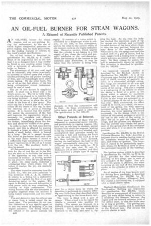
The oil-fuel burner is described in specification No. 195,725 by J. Leslie. Much of its importance lies in the faot that it is so designed that it may.. readily be fitted to any existing steam wagon, with a minimum of alteration to the boiler or firebox.
The advantages of oil over, coal need not be laboured.; they relate principally to economy of bunker space and weight., besides providing for the quicker kindling of fires, and correspondingly more rapid steam raising. On the other hand, the use of oil as the fuel allows of the fire being extinguished almost instantaneously in case of need.
The jet of this burner is simplicity itself. A small cup is fitted with a lid which screws on. The lid is fairly deep, and is also cup-shaped in its interior, the cup being inverted. A small hole in the top of the lid serves to allow the oil to exude in the form of a fine spray. The main cup has a branch pipe to it, which enters off the centre of the cup, so that the entering oil is givers a whirling motion. It is claimed that this materially assists the atomization of the fuel and improves the vaporization which is necessary for complete and efficient combustion. The jet is located inside the firebox immediately above the firebars and about the middle of the grate.
In order to start, the fuel must first be heated, and this is effected by passing it through a brass or other coil located inside a small boiler, which is heated by. a lamp. The oil is passed through this boiler or pre-heater until such time as the main boiler furnace is raised to a sufficiently high temperature to ensure proper-vaporization of the oil as it issues from the jet. The auxiliary boiler is then by-passed.
All the connections between the supply tank for the oil and the jet in the firebox are such as to facilitate the removal of the apparatus at any time with a minimum of trouble. A stirrup, secured by one setscrew, holds the jet and fittings in place; the other parts, including a substantial filter which cleans the oil before it reaches the jet,. are similarly
accessible.
The other invention emanates from the L.G.O. Co., who are joint patentees in this invention with A. A. M. Durrant. It relates to a fitting for a carburetter designed to regulate the flow of an antidetonating agent to the engine. The agent is devised to prevent detonation in such power units as may sometimes be working at high compression. This fitting ensures that the anti-detonator is properly supplied when the mixture is being highly compressed, and not otherwise.
The anti-detonator may be exhaust gas or steam from a jacket round the exhaust pipe. The patentees do not confine themselves to any specific' agent or to any one means of applying it to the . engine cylinders. The fitting which is the subject of the patent controls the
B48
supply. It consists of a valve which is controlled by a. diaphragm which is subject, on one side, to the atmosphere, and on the other to the suction which at the mement exists in the engine induction pipe. Excessive suction, which implies that the cylinder is not taking in a full supply of gas, closes the valve and prevents admission of the anti detonator. When the intensity of the vacuum in the induction pipe diminishes, it may he taken that the cylinder is being fully
charged, so that the compression will be high. In those circumstances the valve opens and the agent is admitted. The specification is No. 195,)37.
Other Patents of Interest.
There must be-few of those who are interested in commercial motor vehicles, and particularly in tipping wagons, who have not, at one time or another, envied the ease with which the wagoner, wishing to tip the contents of a two-wheeled cart, accomplished that operation merely by removing a bolt and backing the horse in to the spot where the load is to he left, then walking the horse forward, leaving the load behind, the body of the wagon automatically returning to the horizontal as the horse walks on. It is clear, at any rate, that W. and F. Dickinson are of that number, and they .haVe invented a .simple type of tipping
gear for a motor lorry by which the operation is performed in a manner differing very little from that described above as appertaining to the horse-drawn cart.
The lorry is fitted with a pair of sprags. When a load is to be tipped the vehicle is reversed into position for tipping. The sprags are lowered, in a forward direction, and the vehicle driven forward. The sprags are coupled by linkwork to the body and .raise it, tip ping the lead. By the time the body has reached the maximum angle of tip the sprags are vertical, and continued forward motion of the lorry allows them to take the rear position, bringing the body down to the horizontal. again. When not in use, the sprags rest upon the hooked ends of a pair of levers, and by their weight hold .a locking bolt in place which prevents movement of the vehicle body. On their release for action, the bolt is automatically drawn by springs. This invention is described in specification No. 195,819.
An Unproved rebound snubberis described by Sir Herbert Austin in stecification No. 195,747. It is of the wing-pump type, having a pair of wings, both of which revolve, or partially re. volve, in a substantial oil-tight casing. The -Wings are attached to an arm and oscillate with it about a pivot in the centre of the casing. The arm is coupled to a road spring of the vehicle on which the device is fitted ata point in the spring which is subject to maximum vibration and moves with that spring. 'Valves in the wings are arranged so as to permit passage of the oil in one direction only. Thus constructed, the effect would he to retard, as a whole, the movement of the spring, one wing opposing movement of the spring in an upward direction the other opposing downward movement. In the design which is the subject of this patent passages or grooves are cut in the walls of the • casing to allow the oil to pass the edges of the wings, and the grooves are designed so that the snubber only checks the movement of the spring after it has oscillated once and when.it is at about its middle position.
Specification No. 195,739, by the British Thomson-Houston Co., Ltd., describes a magneto electric machine having some of its armatures wound for lighting current, and others for ignition. The invention is stated to be particularly applicable where the flywheel is used to carry the permanent magneto or the windings.
The ignition system which is described in specification No. 195,721, by W. G. M. Ross, provides for the simultaneous sparking of two plugs, one in each of two cylinders of the engine. One only of the two sparks is effective, the other occurring at. the end of the scavenging stroke in the cylinder in which it takes place.
An oil engine of the type largely used for driving barn machinery is described in specification No. 195,788, by W. -Guthrie and Wallace {Glasgow), Ltd. The engine, a horizontal one, is equipped with a single-sleeve valve.
Maybach-Motorenbau Gesellschaft Mit Beschrankter Haftung are responsible for specification No. 169,713, which describes an arrangement of transmission gear, the main object being to reduce to a minimum the distance between the engine and the forward universal joint of the cardan shaft, so that the latter may be as long as possible. The gearing provides only two speeds, and is embodied in the flywheel ease. For reverse the electric starter is used. •